R 02/92
Matching Module for Incremental Encoders
3.3.5
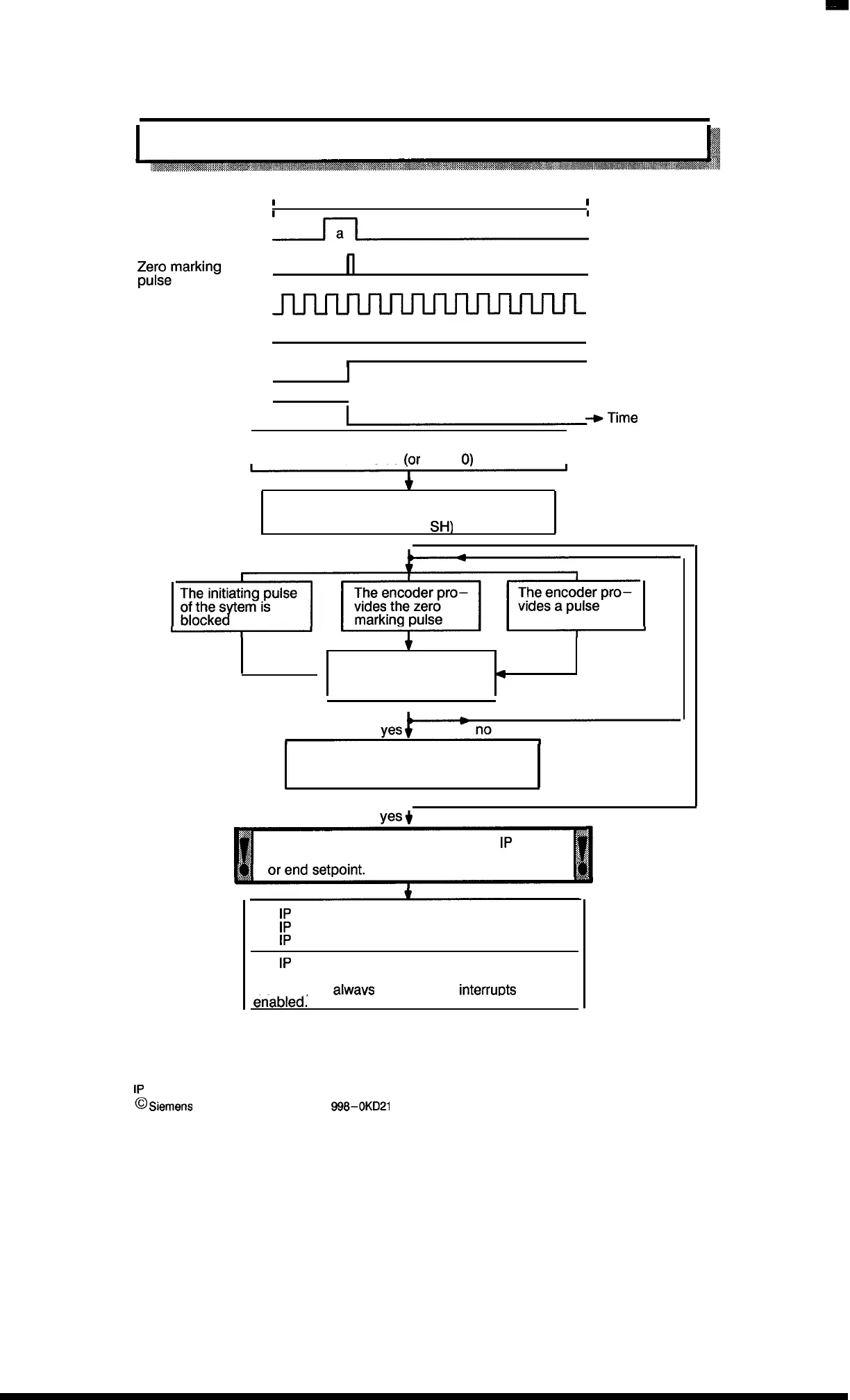
Hardware Synchronization
1
Path
1
I
I
Initiating pulse
Counter pulse
Synchronization
I
pulse
)
Synchronization bit
I
a: maximum of 1
encoder revolution
Pulse diagram
Synchronization
instant
Synchronization LED
~+Time
I
The data block (IP 241) is set with an
NV value
(or
left at
0)
I
*
The hardware synchronization is called
(e.g., by the standard function block with
command
SH)
t
Simultaneously (e.g., by
●
the reference point drive
4
of the system)
The drive direction coincides with the
synchronization direction selected
with switch S2
I
yes+
no
To update the track identifier bits, the
1P
241
requires 1 msec. for each specified start
The
1P
241 sets the synchronization bit
The
1P
241 dims the synchronization LED
The
1P
241 provides the NV value as actual value
The
1P
241 causes an interrupt if the NV value is
greater than an entered set value with interrupt
identifier, or
alwavs
when the NV
interrurXs
are
en”abledl
“
1P
241 Equipment Manual
@
Siemens AG 1989, Order No.: 6ES5
998-0KD21
3–7
Artisan Technology Group - Quality Instrumentation ... Guaranteed | (888) 88-SOURCE | www.artisantg.com

 Loading...


