R 02/92
Matching Module for Incremental Encoders
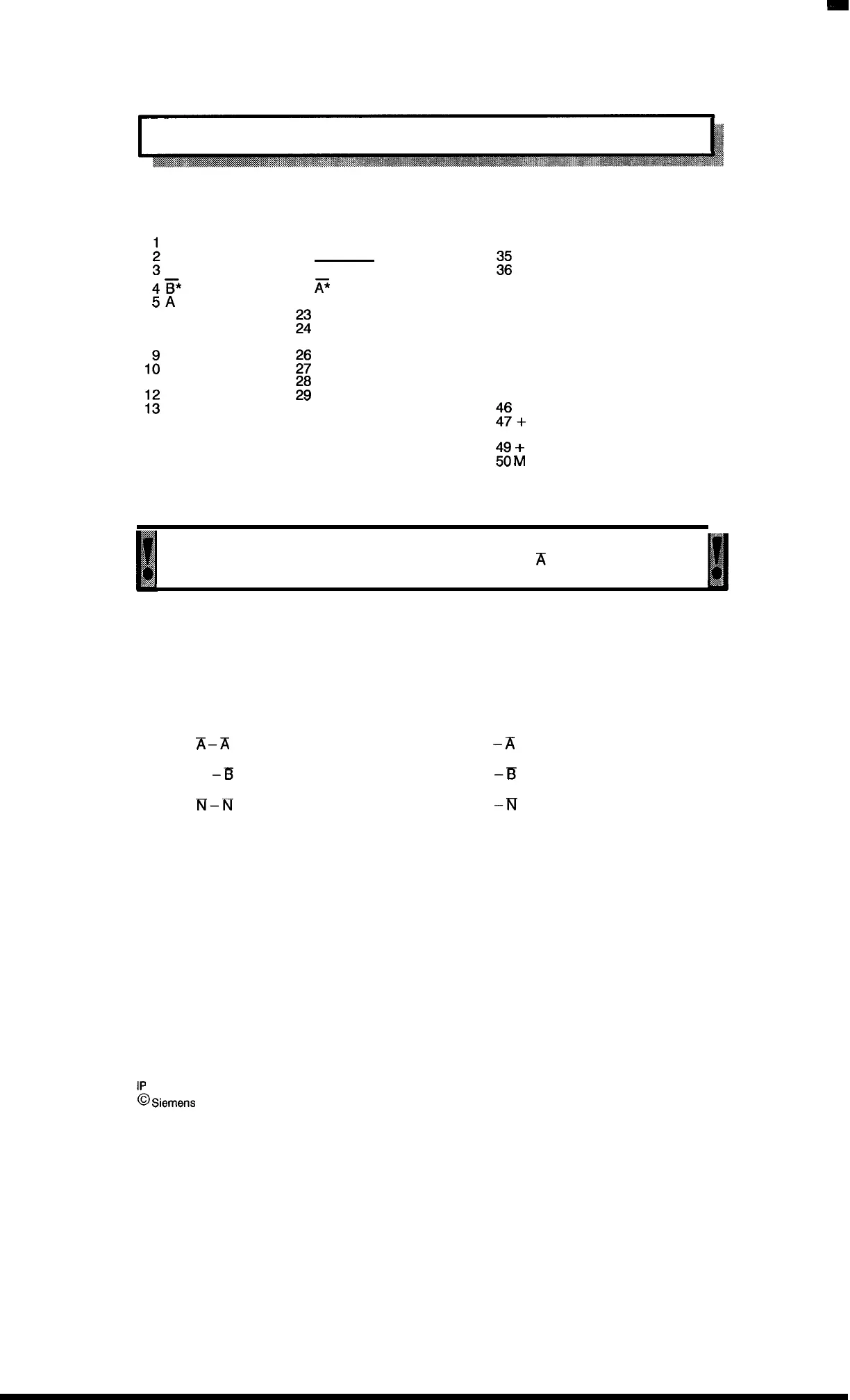
3.3.4 Connector Assignment
Assignment of the sub D connectors (channel 1 or 2)
4F*
5A
6
7
8
1;
11
;:
14
15
16
17 M
18
19
20 Zero marking pulse
21
K’
22
;:
25
$;
;;
30
31 + 5 V/12115
32
33 M
34
%
Zero marking pulse*
37 B
38
39
40
41
42
43
44
45
:;+
5 V/12/15
48
$
~
24 V (output)
Pin 31/47 and pin 17/33/50 are parallel and can be used alternatively.
ml
,’
* For encoders which do not permit all six signals, asymmetrical operation applies!
:
“’”
n
Encoders with only 3 signals must be connected to inputs
X
(pin 21), B (pin 4) and the
,
,,
,,,<::
zero marking pulse (pin 36).
Ill
Symmetrical operation
- Asymmetrical operation
(incremental encoders)
(incremental encoders)
(Improved noise immunity)
Six encoder signals on
Three encoder signals on
50–way sub D connector
50–way sub D connector
Signal A –A PIN 5
Signal
X
–A
PIN 21
Signal A
–X
PIN 21
Signal B – B PIN 37
Signal 13
–E
PIN 4
Signal B –El PIN 4
Signal N – N PIN 36
Signal
N
–N
PIN 20
Signal N
–N
PIN 36
1P
241 Equipment Manual
@
Siemens
AG 1989, Order No.: 6ES5 998-0KD21
3–5
Artisan Technology Group - Quality Instrumentation ... Guaranteed | (888) 88-SOURCE | www.artisantg.com

 Loading...


