R 02/92
General Function Description
1.5
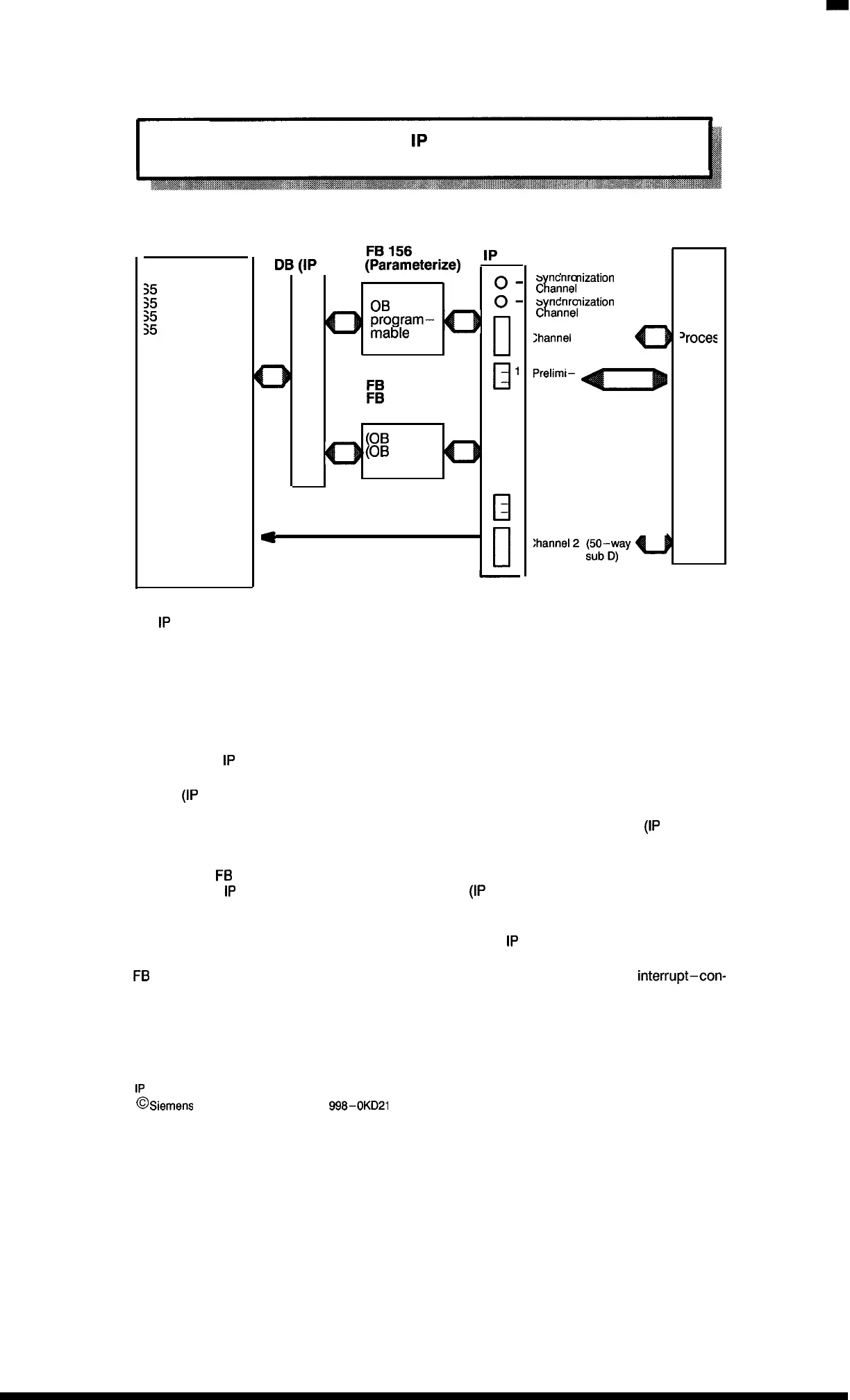
Communication between
1P
241 Digital Position Decoder
and Programmable Controller
Programmable
Controller
35
– 115U
35
– 135U
>5
– 15os/u
35
– 155U
DI
o
(IP
—
1P
241
241)
~p~~~~eterize)
0.
New start
OB
for the
o-
program–
mable
controller
o
0
El
1
FB
157 or
2
FB
158
(Control)
~
‘1
OB
1)
OB
2 to 9)
Q
—
d
Interrupt lines
II
S
nchronization
LED
Cltannel
1
S
nchronization
LED
Clannel 2
;hannel
1 (50–way
sub D)
a
Prelimi–
nary
contact
I
+ 24 V external
M external
—
‘roces
The
1P
241 communicates with the programmable controller via two standard function blocks. Fur-
thermore, controller–specific interrupts can be transferred to the programmable controller via in-
terrupt lines or group interrupts (byte O).
The function block accesses a data block. With this data block and with the standard function
blocks the user can
– Parametrize
– Control and
– Monitor the
1P
241.
The DB
(IP
241) contains all parameters (e.g., cam setpoints, interrupts).
The data block number can be selected by the user; the data sequence in the DB
(IP
241) must
then be strictly adhered to!
The standard
FB
156 (parameterize) is called in the new start OBS of the programmable controller.
It supplies the
1P
241 with the data specified in the DB
(IP
241).
FB 157 (control) is called in the cyclic program and/or in the interrupt–controlled program. The
commands given there serve for controlling or scanning the
1P
241.
FB
158 (control–indirect parameterization) is also called during the cyclic and/or
interrupt–con-
trolled program. In contrast to FB 157, the parameters are transferred indirectly via the working
data block.
1–5
1P
241 Equipment Manual
@
Siemens AG 1989, Order No: 6ES5
998-0KD21
Artisan Technology Group - Quality Instrumentation ... Guaranteed | (888) 88-SOURCE | www.artisantg.com

 Loading...


