R 02/92
Matching Module 2 for Absolute Encoders
I
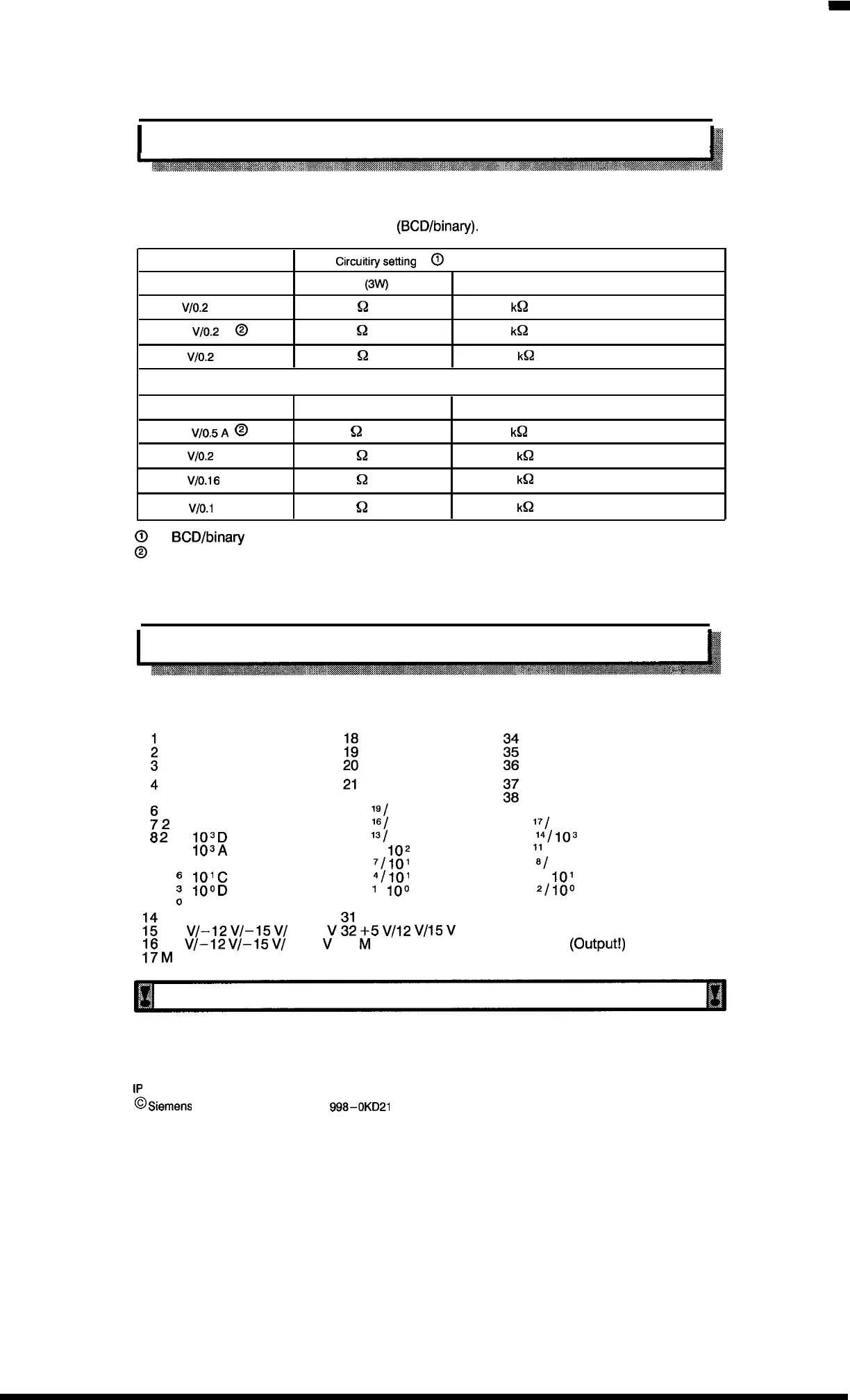
5.3.3 Setting the Encoder Power Supply
k
,,
The required encoder supply voltage must be provided by suitable adjustment of the circuitry on
the absolute encoder matching module 2
(BCD/binary).
Required voltage
Circufiirysetiing
0
R13
(3W)
R20
+ 5
V/O.2
A
180
~
33
k~
+ 12
V/O.2
A
@
330
Q
91
k~
+ 15
V/O.2
A
330
Q
120
k~
+ 24 V/2A corresponds to external system voltage from Faston connector
R5
R4
-5 VI0.5A
@
82
~
51
k~
– 12
V/O.2
A 330
Q
120
k~
– 15
V/O.16
A
330
Q
150
k~
– 24
VIO.I
A
470
Q
240
k~
@
See
BCD/binary
layout, section 5.3.5.
@
State as delivered
A current limiter for 0.2A is available for the positive supply.
5.3.4 Connector Pin Assignment
Pin assignment of the sub D connector (channel 1 or 2)
5
;
2
Is
8
z
15
9212
102
9
112
6
122
3
132
‘J
22
232
19/
10
4
D
10
4
c 242
IG/
10
4
A
103
D
252 ls/ 10
3
B
103/4
262 ‘
0
/
102
C
10
2
B 272 7/101 D
101
c
282 4/101 A
100
D
292
1
/
100
B
IO
O
A
30
;:
–5
VI–12
VI–15
VI –24
V
:;
+5
VI12
VI15
V
16
–5
VI–12
VI–15
VI –24
V
33
M
17
M
39
402
17/
10
4
B
41 2
14/
103
c
422
“ / 10
2
D
432
61
10
2
A
442 s/
101
B
452
2/
100
c
46
47
48 + 5 V/12 V/15 V
49 + 24 V
(Output!)
50 M
Unused inputs must be connected to ground (M–potential)!
1P
241 Equipment Manual
@
Siemens
AG 1989, Order No.: 6ES5
998-0KD21
5–5
Artisan Technology Group - Quality Instrumentation ... Guaranteed | (888) 88-SOURCE | www.artisantg.com

 Loading...


