Matching Module 2 for
Abaolute
Encoders
R
02/92
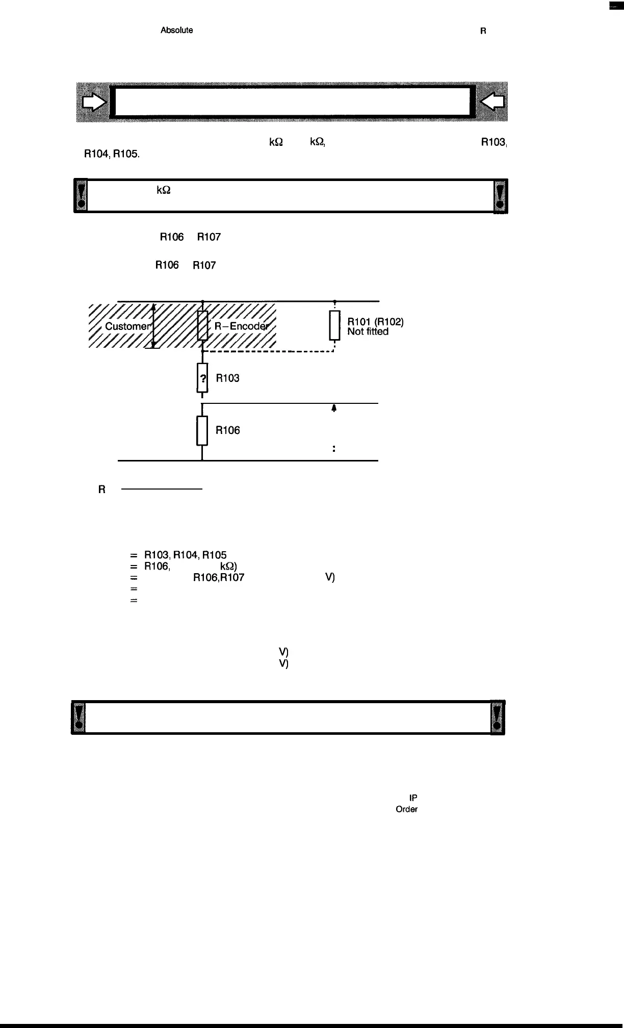
Instructions for conditioning the input circuitry
– In the encoder impedance range from 6
k!d
to 10
k$l,
wire jumpers can be inserted for
R103,
R104,
R105.
El
~:
– Below 6
kQ
encoder impedance, the resistor networks must be individually
{
computed.
Ill
,,,,
– The high level at
R106
or
R107
must be between 3 V and 5 V.
– The low level at
R106
or
R107
must be below or equal to 0.8 V.
+ 24 V
-
.
-----------
.--.-.-J
?
R103
(RI O4IR1O5)
h
4
: U 2 minimum = 3 V
R106
(R107)
M
:
U 2 maximum = 5 V
*
– R2 X (U – U2)
U2
– R–Encoder
Explanation:
R
=
R2
=
U2
=
u
R–Encoder
:
R103,
R104,
R105
R106,
RI 07 (1 .5
kQ)
Voltage at
R106,
R107
(min. 3 V, max. 5
V)
Encoder voltage (24 V)
Encoder impedance (see label or data sheet)
How
to proceed:
a) Compute the value R max. with U2 min. (3
V)
b) Compute the value R min. with U2 max. (5
V)
c) Select the resistor network according to E–series (between R max. and R min.)
1111
p:
,
Only resistor networks consisting of single resistors maybe used.
See the technical specifications, section 8.6.
n
5–4
1P
241 Equipment Manual
@.SiemensA(31989, order No.: 6ES5898-0KD21
Artisan Technology Group - Quality Instrumentation ... Guaranteed | (888) 88-SOURCE | www.artisantg.com

 Loading...


