R 02/92
Matching Module 4 for Absolute Encoders
7.3 Putting into Operation
Components required:
Basic module
1P
241 (order no.6ES5 241 –lAA11) firmware version A07 or later,
Absolute encoder matching module 4 synchronous–serial
(order no.
6ES5
241 -l AF1l) -1 each per channel
Component set absolute 4 synchronous–serial
(order no.
6ES5
271–lAF1l) – 1 each per channel
External voltage supply 24 V (Connection to the Faston connector on the basic module)
The following settings need to be checked and adjusted if necessary:
—
—
—
—
—
—
—
—
.
Shielding (interference suppression)
Encoder supply voltage (resistor
R31)
Sense line on encoder connected or open (see 7.3.5)
Selection of input signal interface (via receiver or opto coupler/switch S2)
Wave resistance R2 for operation via receiver
Code setting for encoder (jumper
BR1)
Control bit setting (switches S4 and S1)
Actual value transfer mode to the PLC (switches
S5.1
and S5.2)
Presetting the number of clock–pulse groups
(TB)
via the standard function block or
according to parameterization example
7.3.1 Setting the Operating Mode
7.3.1.1 General
COMMENT TO SWITCH “S5”!
The switches “S5.1” and “S5.2” ARE SCANNED BY THE BASIC MODULE ONLY! The switch posi-
tions inform THE BASIC MODULE ALONE whether the software-based
BCD
conversion is to be
quick or slow and/or whether no dual (binary) to
BCD
conversion is to take place at all!
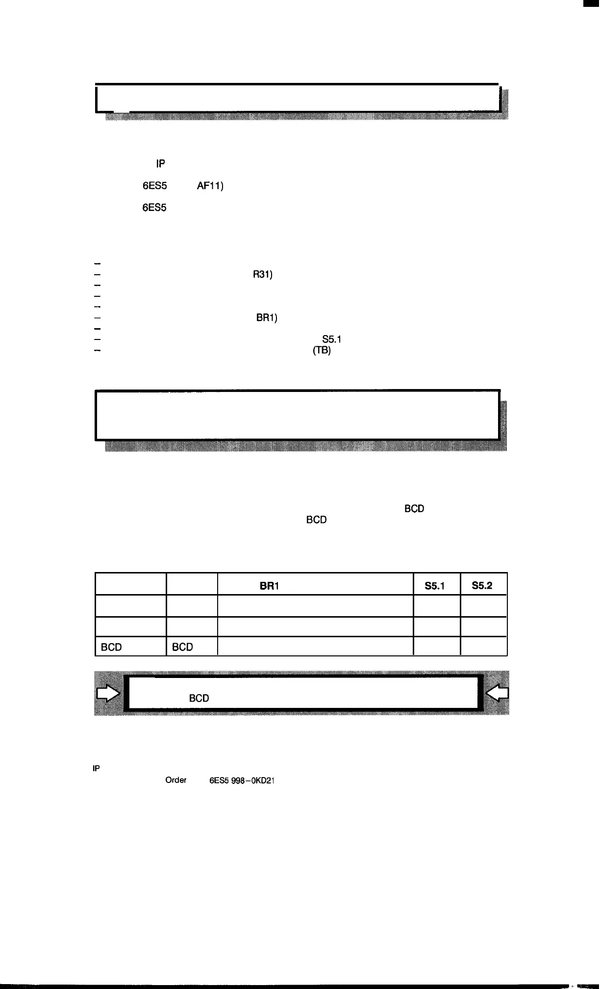
In order to obtain short processing times, it is recommended that you work with the follow-
ing formats:
Actual values
Setpoints
Jumper
BR1
encoder matching module
S5.I
S5.2
Gray Code
Binary Position “Gray”
Closed Closed
Binary
Binary
Position “BIN/BCD”
Closed
Closed
BCD BCD Position “BIN/BCD”
Closed Closed
This eliminates the conversion times on the basic module
(i.e., no
BCD
conversion takes place there).
1P
241 Equipment Manual
@SiemensA(31989,
Order
No.:
6ES5
gg8-0KD21
7–5
Artisan Technology Group - Quality Instrumentation ... Guaranteed | (888) 88-SOURCE | www.artisantg.com

 Loading...


