R 02/92
Operating Instructions
●
Settings for two to eight
1P
241s with interrupt processing
The distinction as to which
1P
has triggered the interrupt can be made by using the so–called
group interrupt (i.e., by output via the peripheral byte O
(PYO)).
By means of the peripheral byte O, a programmable controller can distinguish up to eight posi-
tion decoder modules (IP 241).
For this purpose all modules must be installed in the same central
The group signals are called by parameters 0.0 to 0.7. The group for each module is switched to
the data bus via the contacts of DIP switch
S2.
Master/Slave-Principle:
On the first module, the
master(the
group signal) is routed to bit O of the
PYO;
on the second mod-
ule, the slave is routed to bit 1 of the
PYO
and so on.
Master: On the first module contact
S2.1
must be opened and contact
S2.2
closed.
-t the group signal is only activated on bit O of the
PYO.
Additionally on the DIP switch S2 those contacts which were assigned to the
slave modules as bits of the
PYO
are opened. All
PYO
jumpers which are
not required by a slave must be closed.
Slave:
On the other
1P
241 modules with group signal, these contacts
S2.1
and
S2.2
remain closed.
On the DIP switch S2 of the slave modules, in addition to
S2.land
S2.2
only that contact which will be assigned a corresponding bit of the module’s
peripheral byte O is closed. The other seven S2 contacts on the slave
modules must be opened.
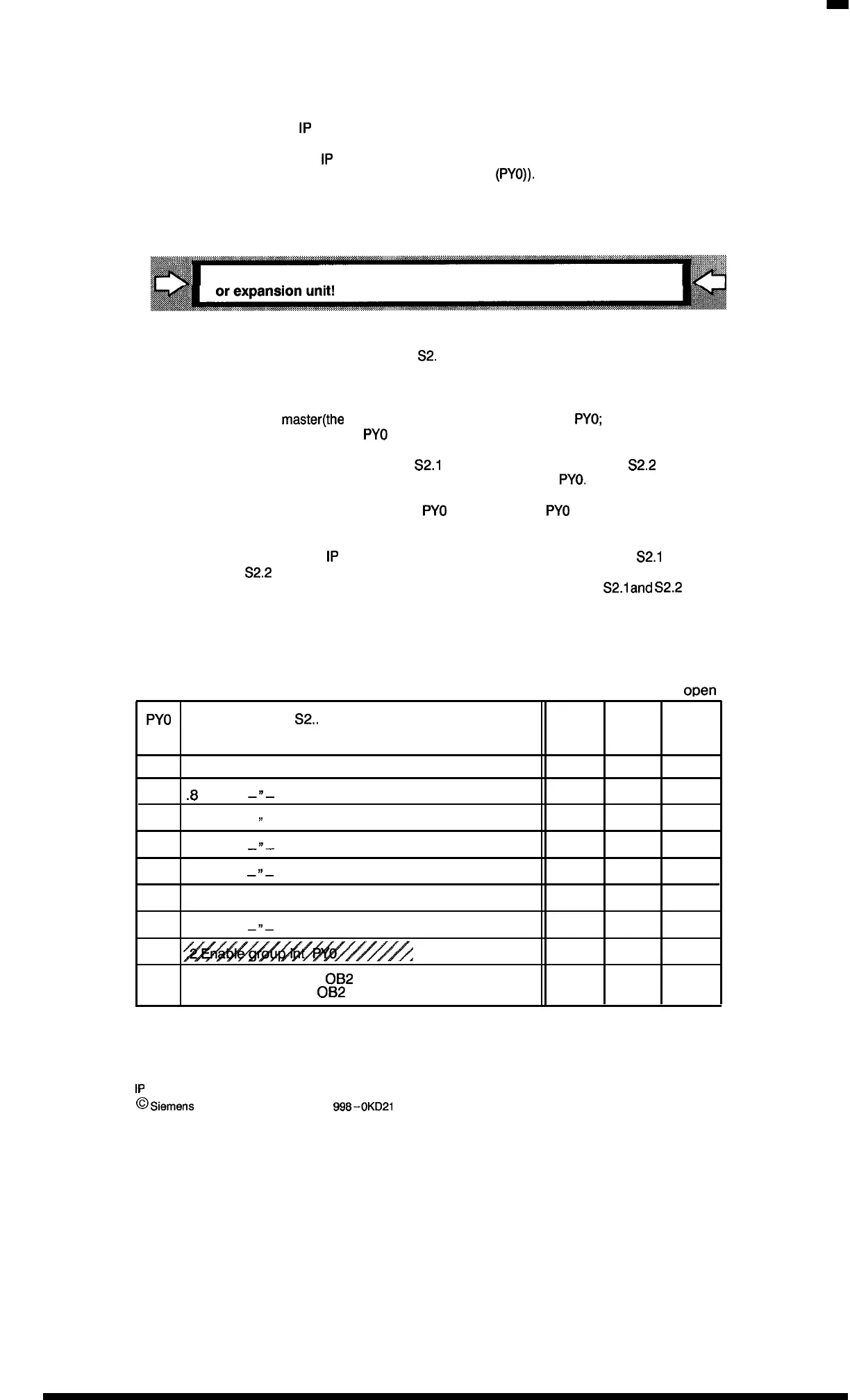
Example:
x = closed
– =
o~en
PYO
DIP switch
S2,.
Master
Slave 1
Slave 6
Bit O
.10 Group interrupt
x
— —
Bit 1
.9 –“-
—
x
—
Bit 2 .8
–“-
X
—
—
Bit 3 .7
—
~’
—
x
— —
Bit 4 .6
—“-
X
— —
Bit 5
.5
–“-
X
—
—
Bit 6
.4 –“-
— —
x
Bit 7 .3
x
—
—
x
x x
.1 Change over: Only
OB2
(o en)
8
—
x
x
or
OB2
to B 9 (closed)
1P
241 Equipment Manual
@
si01W3flS
AG 1989, Order No.: 6ES5 998-0KD21
2–7
Artisan Technology Group - Quality Instrumentation ... Guaranteed | (888) 88-SOURCE | www.artisantg.com

 Loading...


