Operating Instructions
R 02/92
2.5
GeneraI Interrupt Processing with thePLCS5–115U
With the programmable controller S5–115U, the interrupt lines in general are available for inter-
rupt processing.
Via the peripheral byte O it then can be established which module(s) has (have) triggered the inter-
rupt on the line.
The
1P
241 issues an interrupt by activating the interrupt line (e.g., by outputting a low signal). This
is performed in the central unit directly and via interface
IM
307/31 7 with light wave conductor cou-
pling for expansion device ER 701–3 or EG 186U.
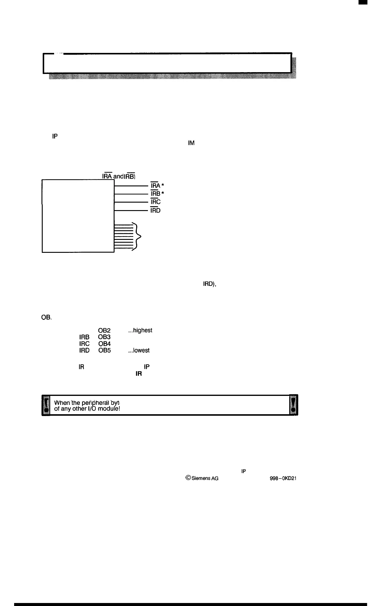
Interrupt organization for S5-115U
(*with CPU 941A only
l~and
IRy)
~:’
Peripheral byte O
Interrupt lines
Interrupt for one 1P 241 module
if only one module (IP 241) is used per interrupt line (IRA to
IRD),
the peripheral byte O must be
disabled (DIP switch S2.1 to S2.1O open) and the interrupt lines must be defined by the corre-
sponding DIP switch S1 setting.
In the CPU, a hardware interrupt on the interrupt line causes a jump to a firmly assigned interrupt
OB.
– IRA to
OB2
...highest
priority
–
IRB
to
OB3
–
IRC
to
OB4
–
IRD
to
OB5
...lowest
priority
One interrupt
IR
line is assigned to an
1P
241 module.
The DIP switches for the interrupt
IR
lines not used by this module must be opened! (Section
2.5.2)
tll
:~
.
j
When the peri heral b e O is used, the address O may not be used in the P–area
~
~
,.
;
ofanyotherl/gmodu#!
Ill
2–8
1P
241 Equipment Manual
@
Siemens
AG
1989, Order No.: 6ES5 888-0KD21
Artisan Technology Group - Quality Instrumentation ... Guaranteed | (888) 88-SOURCE | www.artisantg.com

 Loading...


