R 02/92
Operating Instructions
Interrupt for several
1P
241 modules on one interrupt line
If several
IPs
access one interrupt (IRA to
IRD),
the individual
IPs
must be identified. For this pur-
pose (up to eight units) a specific bit must be allocated in the peripheral byte O for each 1P; (e.g.,
peripheral bit 0.0 for IP1, peripheral bit 0.1 for
IP2
and soon (see section 2.5.2).
If, for example, the peripheral bit 0.0 = 1, the
1P
to which this bit was allocated has triggered this
interrupt.
(PER:
WST)
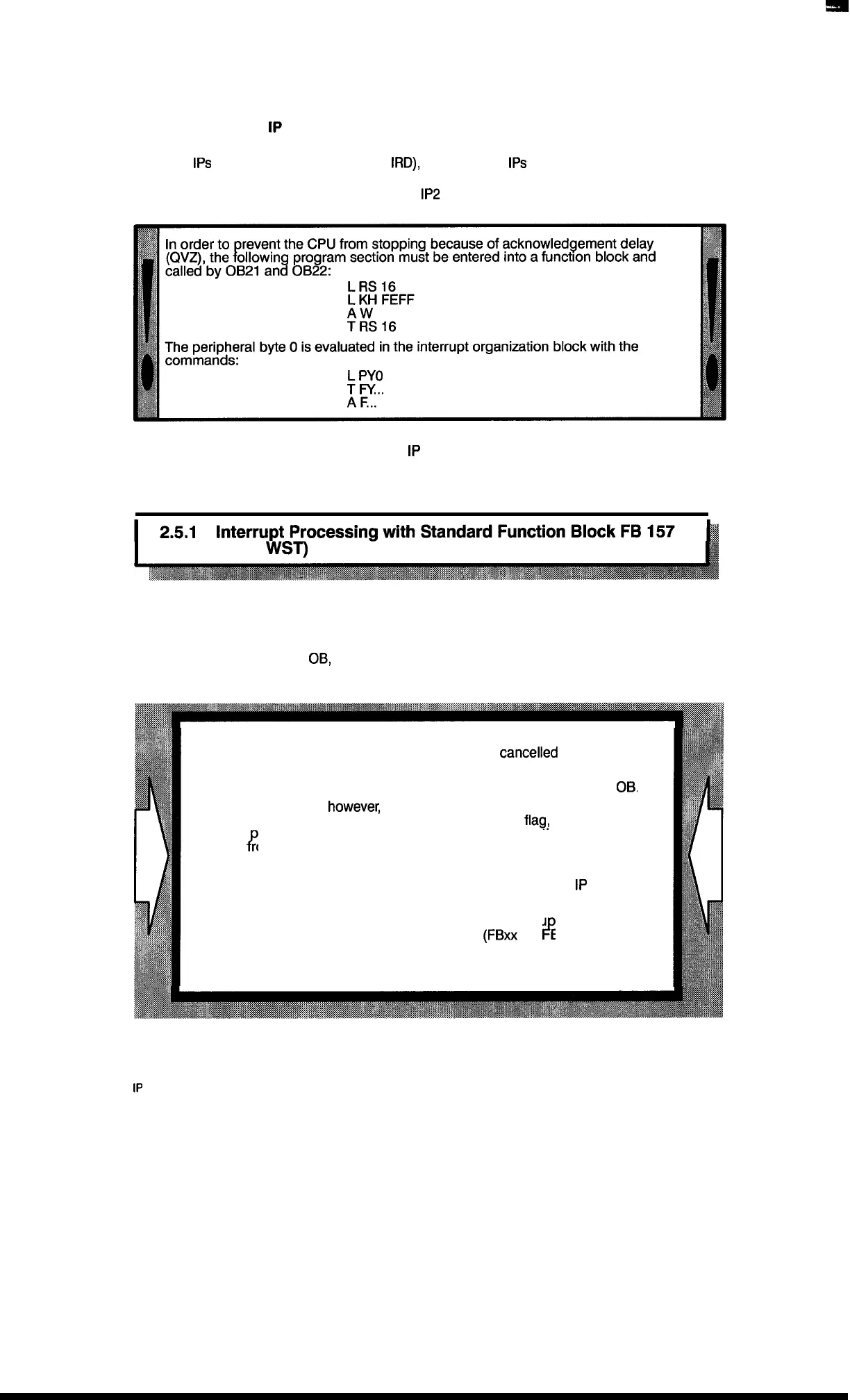
When an interrupt occurs, the pertaining interrupt OB is called. The call for function block FB 157
with
the parameter assignment BEF =
KB is written into this organization block.
After the call by the interrupt
OB,
parameter ST shows from which channel the interrupt originated
(i.e., you can have your specific interrupt program processed then).
If during processing of function block FB 157 in the cyclic program an
interrupt occurs, the roup interrupt at the bus is
cancelled
by FB 157
?
(or by reading byte 7.
Consequently, no interrupt identity bit can be evaluated in the alarm
OB.
In the function block,
howeve~
the control bits are updated, so that
depending on the interrupt identifier bits saved in the
flag!
your specific
interrupt rogram can be called. This means the information about the
/’
channel rom which the interrupt originated is stored in the control
byte (ST).
Therefore after each call of FB 157 in the cyclic program both
IP
241
interrupt bits must be scanned!
After having been evaluated, the control bits in the interru t–OB must
+’
be reset, as otherwise the interrupt programs
(FBxx
and Byy) might
be processed in the cyclic program once again.
This is taken into account in the example in section 2.3.
2–9
1P
241 Equipment Manual
@SiemensA(31989, Order No.: 6ES5998-0KD21
Artisan Technology Group - Quality Instrumentation ... Guaranteed | (888) 88-SOURCE | www.artisantg.com

 Loading...


