R
02/92
Operating Instruction
2.6
GeneraI Interrupt Processing with S5-135U
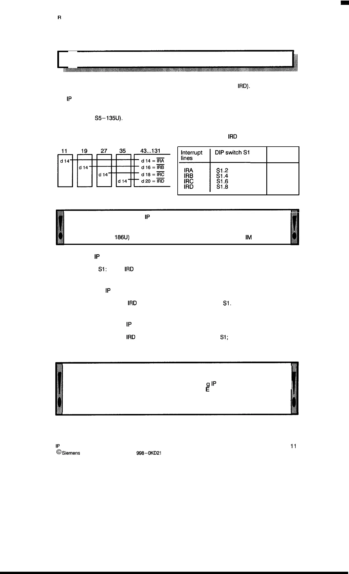
A separate hardware interrupt line is allocated to each CPU slot (IRA to
IRD).
The
1P
triggers an interrupt by activating the interrupt line (i.e., by outputting a low–signal)
In the corresponding CPU a jump to interrupt 062 is effected (for more details see Equipment
Manual for the
S5–135U).
slot
Allocation of IRA to
IRD
via DIP switch S1
CPU 1 CPU 2 CPU 3 CPU 4 Peripherals
t
Interrupt DIP switch S1
lines
IRA
S1
.2
IRB
S1
.4
IRC
S1 .6
IRD
S1 .8
CPU 1
CPU 2
CPU 3
CPU 4
For interrupt processing the
1P
must be inserted into a slot with interrupt line
(slots 43 to 131). See section 8.8.
Interrupts are not possible in the expansion unit unless lines exist there (e.g.,
ER 701–3 or EG
186U)
and the devices are connected via interface
IM
307/317.
. Setting for
1P
241 without interrupt processing
DIP switch
S1:
IRA to
IRD
: OPEN
DIP switch S2: All switches OPEN
●
Setting for one
1P
241 with interrupt processing
One of the lines IRA to
IRD
must be selected with DIP switch
S1.
The switches for the remaining lines must be openad!
●
Setting for two to eight
1P
241s with interrupt processing
One of the lines IRA to
IRD
must be selected with DIP switch
S1;
(the same line for all master
and slave modules).
The switches for the remaining lines must be opened!
The individual modules must be set in accordance with the Master/Slave principle
(see section 2.4).
If several IPs are used on one interrupt line, the triggerin
1P
can be recognized by
1?
evaluating the peripheral byte. For more details see the quipment Manual for your
programmable controller.
Evaluation of the peripheral byte O is only possible if the module is addressed in the
P–area.
2 –
11
1P
241 Equipment Manual
@
Siemens AG 1989, Order No.: 6ES5
998-0KD2t
Artisan Technology Group - Quality Instrumentation ... Guaranteed | (888) 88-SOURCE | www.artisantg.com

 Loading...


