R 02/92
Matching Module 4 for Absolute Encoders
After turning on, the synchronization LED of the respective channel lights up until the clock pulse
group has been transferred to the module. The parameterTB can be transferred in BCD code from
the programmable controller, following the example for parameter assignment.
By means of the standard function block, direct specification of the clock pulse groups is possible.
The parameters are transferred from the basic module to the parameter memory of the encoder
matching module.
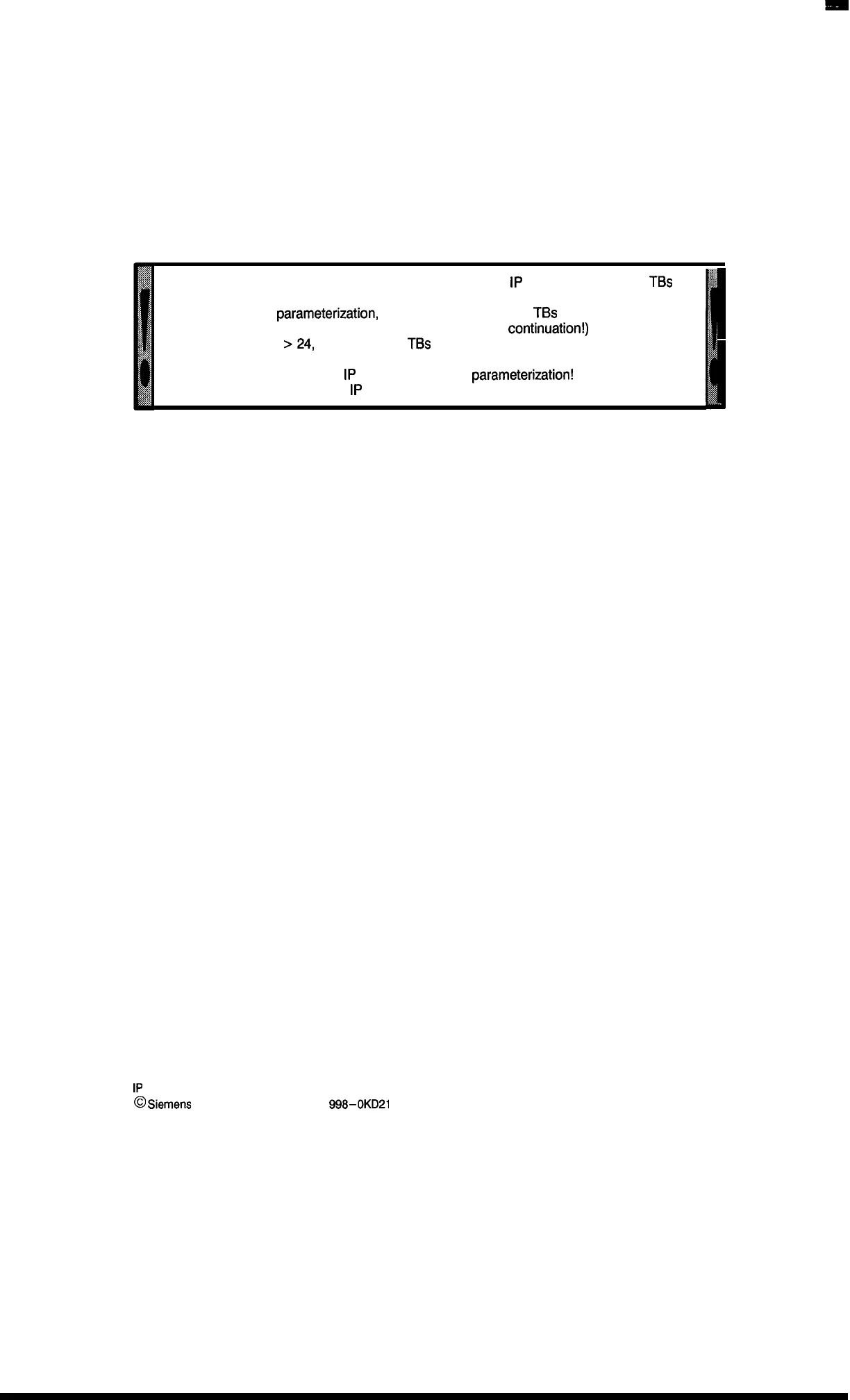
In case of “power on” or “software-based reset” of the
1P
241, the number of
TBs
is internally set to 35!
In case of wrong
parameterization,
the specified number of
TBs
is increased by
two. (Watch out when reading back or during process
continuation!)
For the setting TB
>24,
the number of
TBs
is internally set to 35 and the
synchronization LED lights up.
With each power failure the
1P
241 requires new
parameterization!
This is a condition for correct
1P
241 operation.
1P
241 Equipment Manual
@
Siemens AG 1989, Order No.: 6ES5
998-0KD21
7–3
Artisan Technology Group - Quality Instrumentation ... Guaranteed | (888) 88-SOURCE | www.artisantg.com

 Loading...


