Understanding Module Operation
3-8
High Speed Counter Encoder Module User Manual
3.4 Configuring Program Mode Setup Words
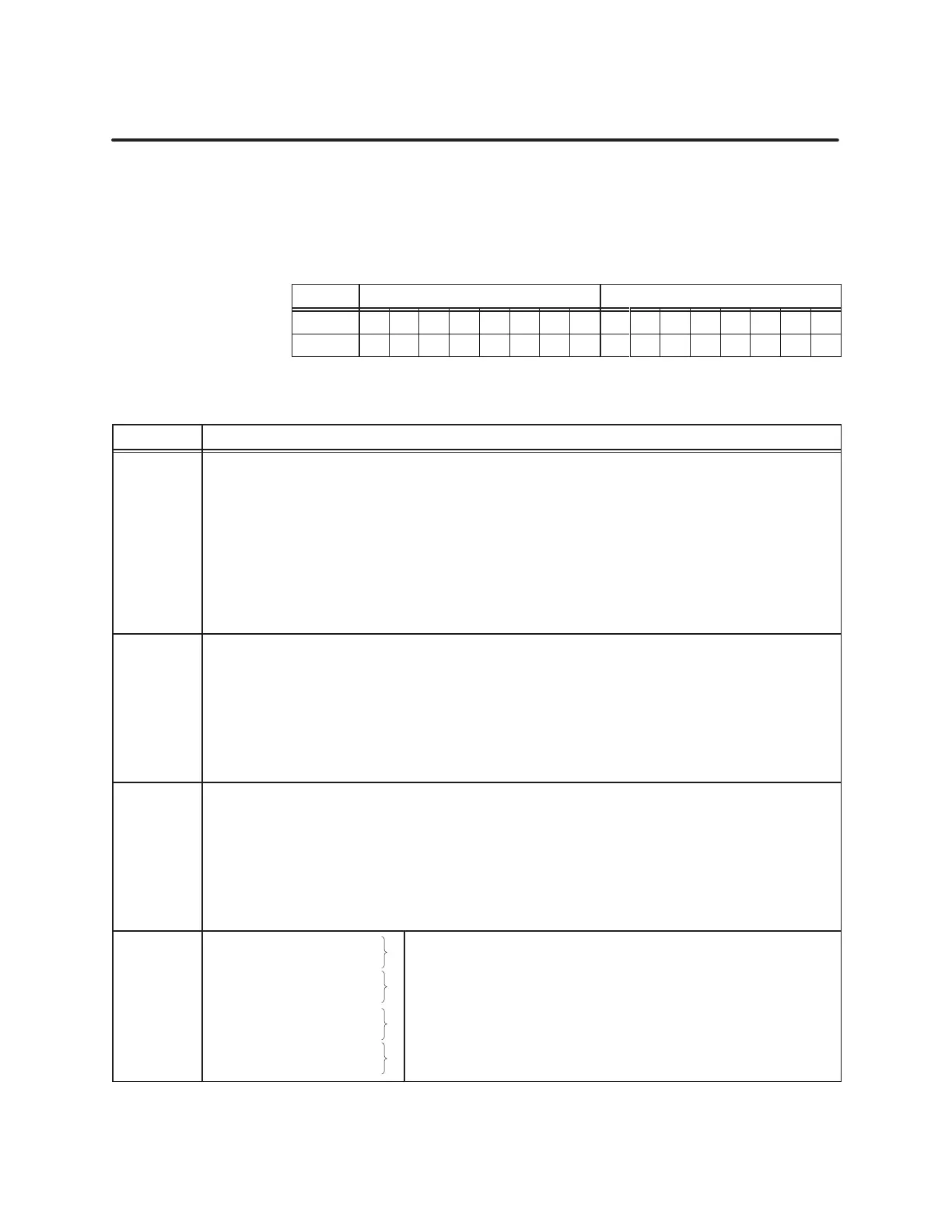
You
can use WY19 and WY20 to choose specific counter input or output
options in Program Mode, as listed in T
able 3-8. (The format is shown in
T
able 3-7.)
T
able 3-7
Module Setup W
ords
Word MSByte LSByte
WY19 1 2 3 4 5 6 7 8 9 10 11 12 13 14 15 16
WY20 1 2 3 4 5 6 7 8 9 10 11 12 13 14 15 16
T
able 3-8
Bit Definitions for the Pr
ogram Mode Setup W
ords
Word.Bit Description of Bit Functions for PROGRAM Mode
WY19.01
WY19.02
WY19.03
WY19.04
WY19.05
WY19.06
WY19.07
WY19.08
At start of Program Mode, all of the counters are inhibited and reset.
Ch1, Counter 1: Inhibit; counting pauses while set.
Ch1, Counter 1: Reset Counter; count value is cleared to 0 when set. Reset and Go function.
Ch1, Counter 2: Reset Counter; count value is cleared to 0 when set. Reset and Go function.
Ch1, Counter 3: Reset Counter; count value is cleared to 0 when set. Reset and Go function.
Ch2, Counter 4: Inhibit; counting pauses while set.
Ch2, Counter 4: Reset Counter; count value is cleared to 0 when set. Reset and Go function.
Ch2, Counter 5: Reset Counter; count value is cleared to 0 when set. Reset and Go function.
Ch2, Counter 6: Reset Counter; count value is cleared to 0 when set. Reset and Go function.
WY19.09
WY19.10
WY19.11
WY19.12
WY19.13
WY19.14
WY19.15
WY19.16
Output 8 interrupt enable bit; Output 8 can trigger an interrupt
Output 7 interrupt enable bit; Output 7 can trigger an interrupt
Output 6 interrupt enable bit; Output 6 can trigger an interrupt
Output 5 interrupt enable bit; Output 5 can trigger an interrupt
Output 4 interrupt enable bit; Output 4 can trigger an interrupt
Output 3 interrupt enable bit; Output 3 can trigger an interrupt
Output 2 interrupt enable bit; Output 2 can trigger an interrupt
Output 1 interrupt enable bit; Output 1 can trigger an interrupt
WY20.01
WY20.02
WY20.03
WY20.04
WY20.05
WY20.06
WY20.07
WY20.08
Program module counters
User 24 V power supply fault fails module
Read and hold counter values on Reset and power-up
Counters 1 & 4: double 16-bit (0) or 32-bit (1) signed integer format
Ch1, 24-bit Counter 1: unipolar (0) or bipolar (1) count format
Ch2, 24-bit Counter 4: unipolar (0) or bipolar (1) count format
Channel 1, 16-bit Counters 2 and 3: Down (0) or Up (1) counting
Channel 2, 16-bit Counters 5 and 6: Down (0) or Up (1) counting
WY20.09
WY20.10
WY20.11
WY20.12
WY20.13
WY20.14
WY20.15
WY20.16
Channel 1, Counter 2: M
1
Channel 1, Counter 2: M
2
Channel 1, Counter 3: M
1
Channel 1, Counter 3: M
2
Channel 2, Counter 5: M
1
Channel 2, Counter 5: M
2
Channel 2, Counter 6: M
1
Channel 2, Counter 6: M
2
16-Bit Counter Mode of Operation:
M
1
M
2
Description
0 0 Retriggerable one-shot
0 1 Divide-by-N
1 0 Square Wave
1 1 Triggered Strobe
Setup
W
ords:
Pr
ogram Mode