Optional Configurations
5-3
High Speed Counter Encoder Module User Manual
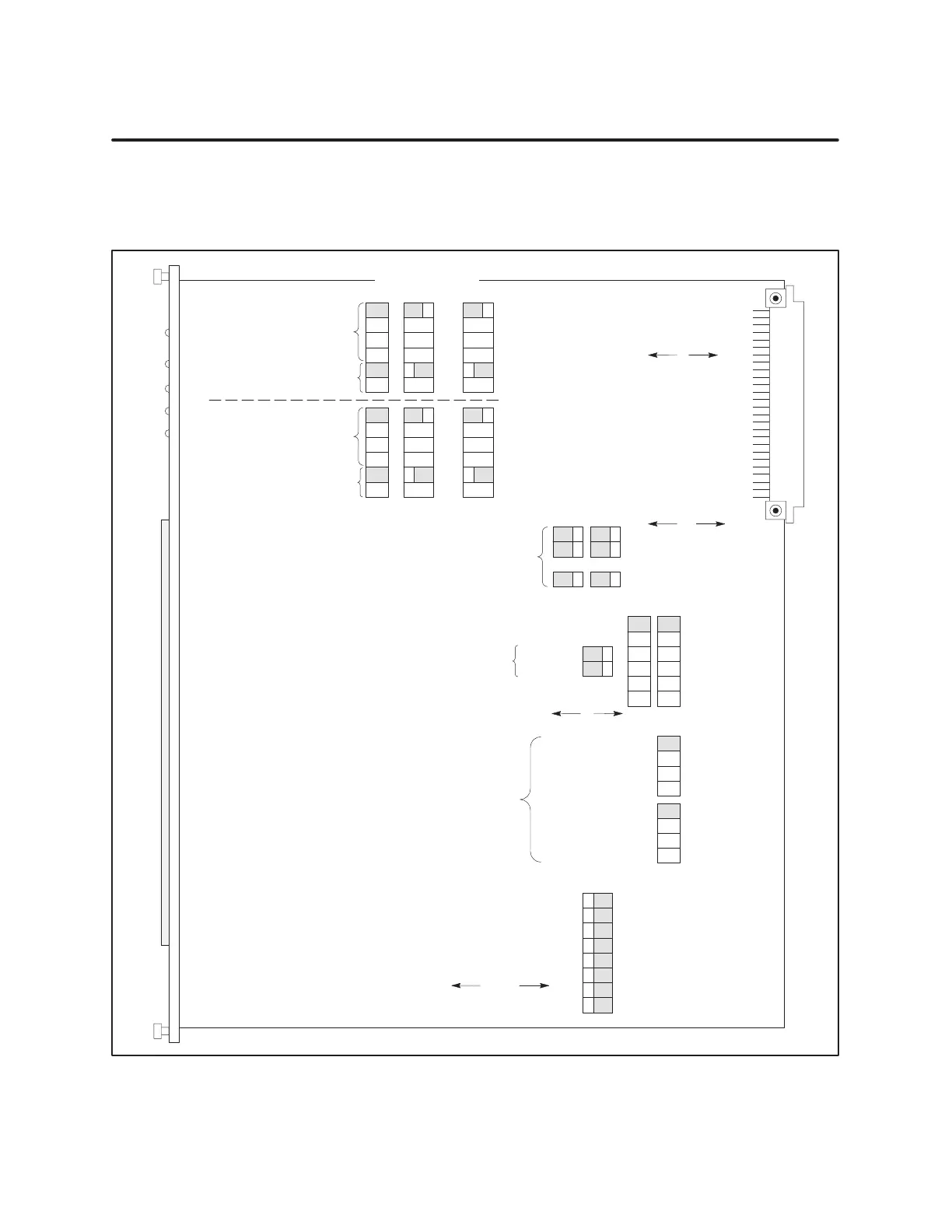
5.2 Configuration Jumpers
An
overview of the jumper locations and functions is shown in Figure 5-1.
Shaded boxes are the default jumper positions. A jumper configuration work
sheet is provided in Appendix B for you to record your jumper settings.
12 3
45 6
MODFAIL
OUTDIS
Hold
Filter:Ch1 Ch2
Counter
1, Output 1
Counter 4, Output 5
Compare
Rollover
Compare T
oggle
Latch
100 kHz
25 kHz
6.25 kHz
1.5 kHz
400 Hz
100 Hz
Ext. Index / Internal Period
Latch / Reset and Go
Inhibit: Level / Edge
Output Polarity:
1
2
3
4
5
6
7
8
Counter
1 (Ch1)
4 (Ch2)
Input
A pulse
1
s internal
Counter 2 output
Counter 3 output
Input B pulse
Up Count Only
Input A pulse
1
s internal
Counter 5 output
Counter 6 output
Channel 1
Channel 2
Counter:
Counter:
Jumper holding position
1
s internal
A input
B input
D input
Counter 5 output
24-bit Counter Output Options:
Output State Mode for Module Failure
or PLC Output Disable Signal:
Counter Inputs:
24-bit Counter Control Signals:
(Channel 1)
(Channel 2)
(Freeze)
Inverted
0 = On
Non-Inverted
1 = On
Clear
(Off)
Compare
Rollover
Compare T
oggle
Latch
Input B pulse
Up Count Only
Gate/Trigger
Input
Clock/Pulse
Input
16-Bit
Counters 2, 3, 5, 6
jumper positions
Jumper
holding position
1
s internal
A input
B input
D input
Counter 2 output
Outputs
—
1
s
A in
B in
C in
cnt3
—
1
s
A in
B in
C in
cnt6
•••
•••
•••
•••
•••
•••
•••
•••
•••
•••
•••
•••
•••
•••
•••
•••
•••
•••
•••
•••
•••
•••
•••
•••
••
••
••
••
••
••
••
••
••
••
••
••
••
••
••
••
••
••
••
••
••
••
••
••
••
••
••
••
••
••
••
••
•••
•••
•••
•••
•••
•••
•••
•••
•••
•••
•••
•••
•••
•••
••••••
Figure 5-1 Jumper
Locations