Understanding Module Operation
3-16
High Speed Counter Encoder Module User Manual
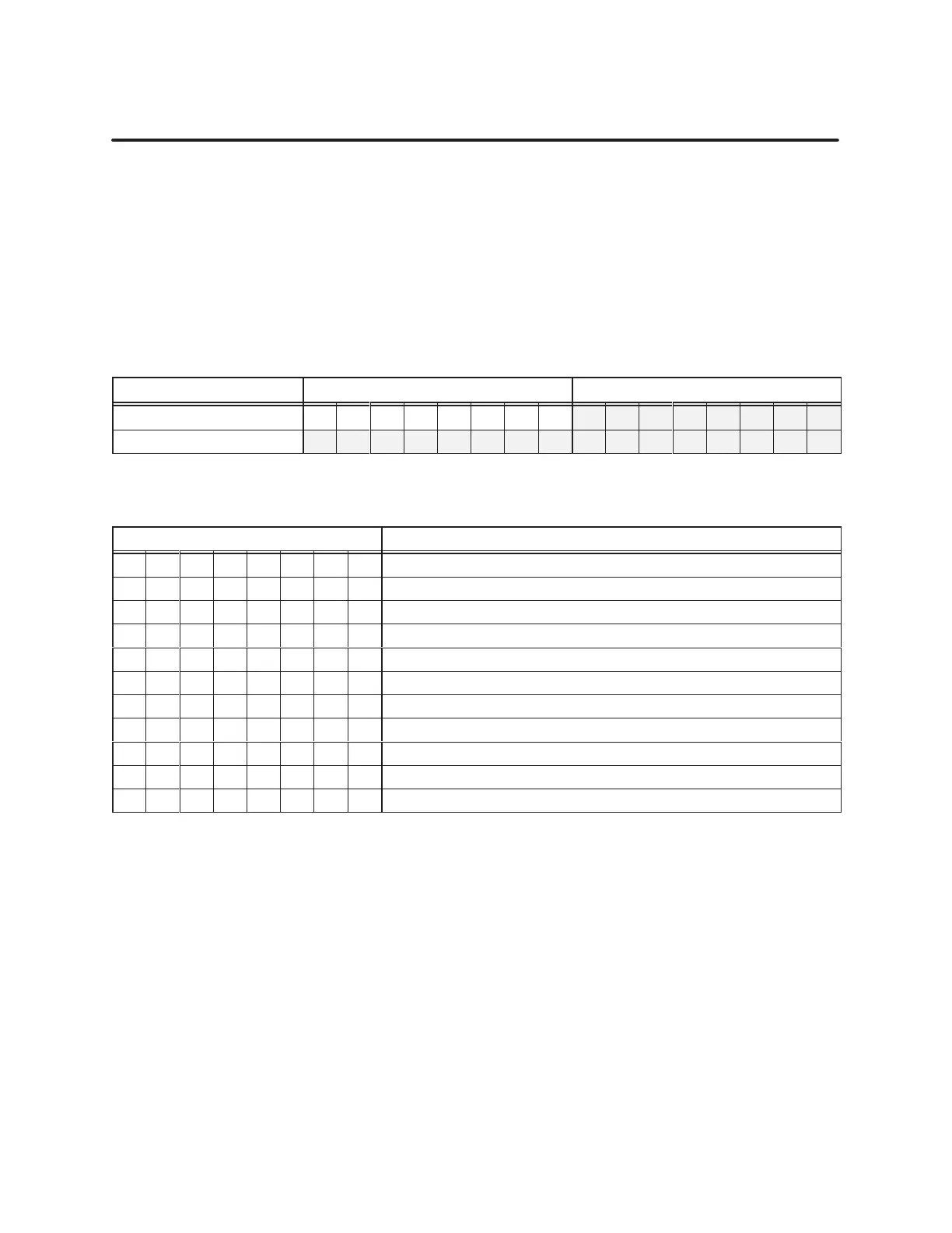
Setting Preset Values and Programming Options for Channel 2 (continued)
The
lower byte of WY29 and all of WY30 contain the 24-bit integer Preset 6
value. Use the upper byte of WY29 to configure programming values.
Together
, the preset value and the programming values determine the count
method and how Outputs 5 and 6 function when the count and preset are
equal, or when the count value is less than or greater than the counter
preset. All preset values are unipolar in format. The shaded areas of
T
able 3-18 show the word formats, and T
able 3-19 lists the programming
values of WY29.
T
able 3-18
Channel 2, 24-Bit Counter: Pr
eset 6 V
alue
Word MSByte LSByte
WY29 1 2 3 4 5 6 7 8 9 10 11 12 13 14 15 16
WY30 1 2 3 4 5 6 7 8 9 10 11 12 13 14 15 16
T
able 3-19
Channel 2, 24-Bit Counter: WY29 Pr
ogramming Bit V
alues
Bit Position Description
01 02 03 04 05 06 07 08
1 Current count updates on an INDEX or PERIOD
0 0 0 0 0 0 0 PLC controls Output 6
1 0 0 0 0 0 0 When Counter 4 value > Preset 6, set Output 6
0 1 0 0 0 0 0 When Counter 4 value < Preset 6, set Output 6
0 1 1 0 0 0 0
When Counter 4 value ≥ Preset 5 and
≤ Preset 6, set Output 6
0 0 1 0 When Counter 4 = Preset 6, set Output 6
0 0 0 1 When Counter 4 = Preset 6, toggle Output 6
1 0 When Counter 4 = Preset 6, clear Counter 4
0 1 When Counter 4 = Preset 6, reload Counter 4 with Preset 5
1 When Counter 4 = Preset 6, clear Output 5 latch
Channel
2,
24-Bit Counter 4,
Pr
eset 6