Product Overview
1-7
High Speed Counter Encoder Module User Manual
1.3 Quadrature Modes of Counting
Each
24-bit counter
, Counter 1 (Channel 1, inputs A & B) and Counter 4
(Channel 2, inputs A & B) provides Quadrature mode counting. When input
A pulses lead input B pulses, the count direction is up. When input B pulses
lead input A pulses, the count direction is down. The relationship between
input A and input B that determines the count direction applies to 1X, 2X,
and 4X Quadrature counting modes, described in this section.
For information on how to configure the module for quadrature counting,
refer to Chapter 5.
Y
ou select one of the three quadrature modes according to the resolution
required by your application and the type of encoder you are using.
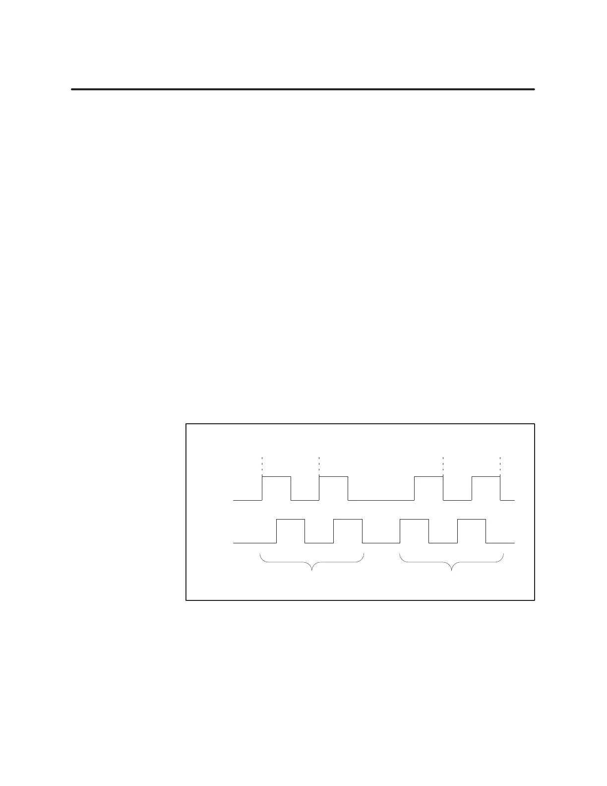
When set to 1X Quadrature Mode, the module counts the rising or the
falling edges of input A pulses, depending on the count direction.
•
When input A leads input B, the count direction is up and the count
value increments on each rising edge of input A.
•
When input B leads input A, the count direction is down and the count
value decrements on each falling edge of input A.
Figure 1-4 shows the relationship between inputs A and B, and the count
value that results using 1X quadrature mode.
Encoder
Pulses
A
B
12 10
Pulse A leads: Count Up
Pulse B leads: Count Down
Counts rising edge of input A
Counts falling edge of input A
Count V
alue:
Figure 1-4 1X
Quadratur
e Mode
Quadratur
e Mode
Overview
1X Quadratur
e
Counting Mode