Product Overview
1-8
High Speed Counter Encoder Module User Manual
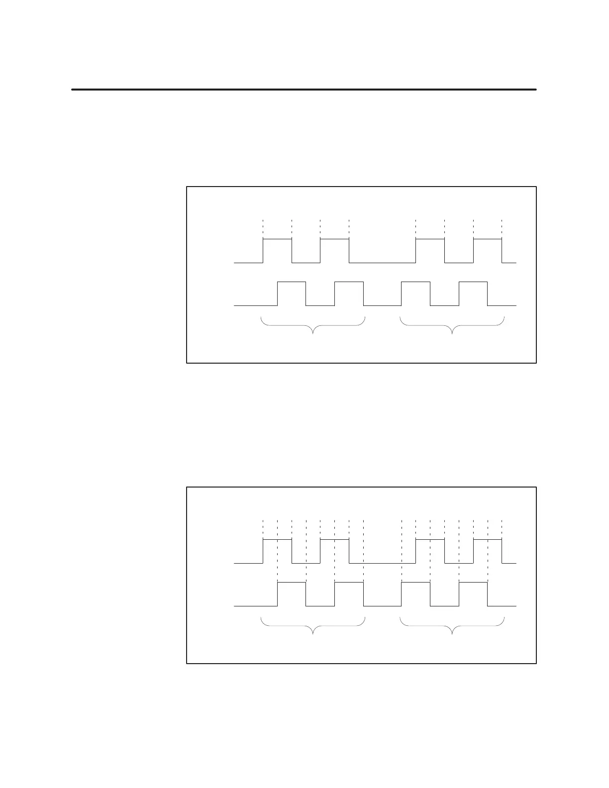
Quadrature Modes of Counting (continued)
When
set to 2X Quadrature Mode, the module counts both edges of input A
pulses, in both count directions.
Figure 1-5 shows the relationship between inputs A and B, and the count
value that results using 2X quadrature mode.
A
B
12 2 0
Pulse
A leads: Count Up
Pulse B leads: Count Down
Counts both edges of input A
Encoder Pulses
Count V
alue: 34 3 1
Figure 1-5 2X
Quadratur
e Mode
When set to 4X Quadrature Mode, the module counts both edges of both
input A pulses and input B pulses, in both count directions.
Figure 1-6 shows the relationship between inputs A and B, and the count
value that results using 4X quadrature mode.
A
B
13 4 0
Pulse
A leads: Count Up
Pulse B leads: Count Down
Counts both edges of both inputs A and B
Encoder Pulses
Count V
alue: 57 6 22 4 6 8 7 5 3 1
Figure 1-6 4X
Quadratur
e Mode
2X Quadratur
e
Counting Mode
4X Quadratur
e
Counting Mode