Installing the Module
2-8
High Speed Counter Encoder Module User Manual
Wiring the Module (continued)
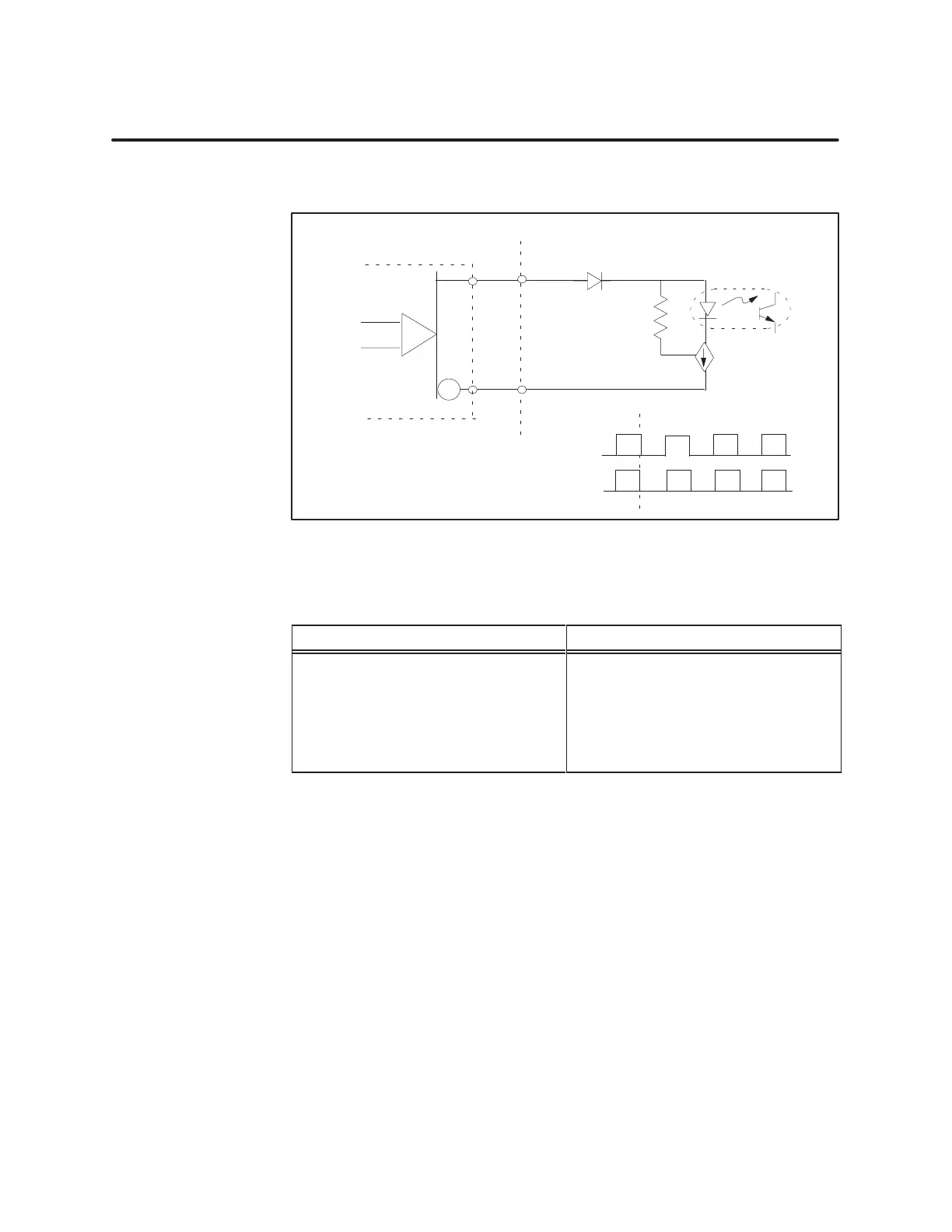
Figure 2-6
shows an example of wiring differential line drive inputs.
A+
A–
Input
Encoder
Module
OCI
Constant
current
load
Input
OCI
On
+
_
Figure 2-6 Differential
Line Drive
T
able 2-2
Featur
es of Electronic Drives
Open Collector or Single-Ended Differential Drives
• 5 to 24 V
• Source or sink
• Polarity selection
• Multiple input drive capability
• Can drive long cable lengths
• Normally 5 V
• Polarity selection
• Voltage and current ratings may
not drive input.
• Active on and off drive

 Loading...


