Installing the Module
2-10
High Speed Counter Encoder Module User Manual
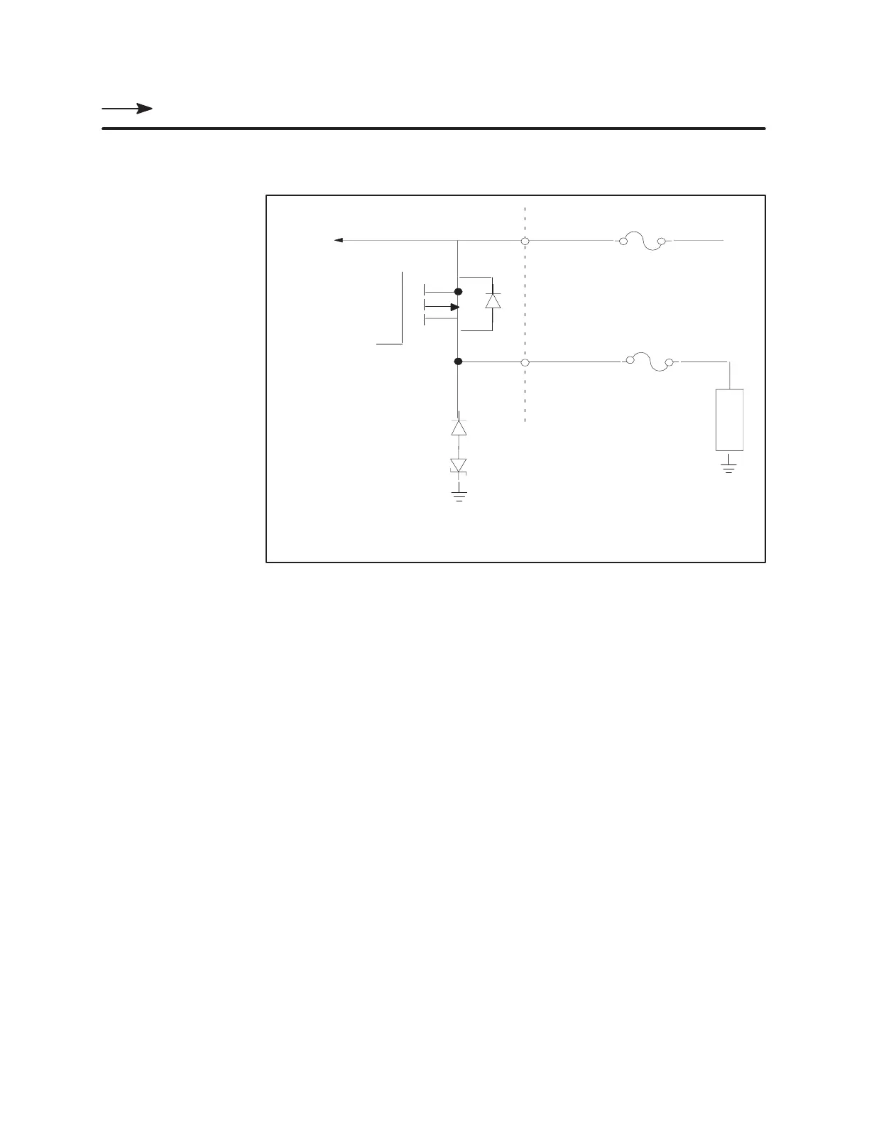
Wiring the Module (continued)
Figure 2-8
shows an example of output wiring.
Load
+24
V
Power supply fuse:
100 mA + Total Load Current*
Output Drive
T
o 7 other outputs
Inductive
Load
Protection
Output fuse:
Rated load current*
*External fuses provided by user must conform to
accepted wiring practives required by the installation.
Figure 2-8 Output
W
iring
W
iring the Outputs