Optional Configurations
5-12
High Speed Counter Encoder Module User Manual
5.7 24-Bit Counter Software Setup Options
After
you configure the hardware jumpers, select the associated bits in both
the preset and setup words to enable the functions. There are four preset
words (WY21 through WY24) and two setup words (WY19 and WY20)
associated with the 24-bit counter
. Refer to T
able 5-3 through T
able 5-7.
Presets 1 and 2 (WY21 through WY24) for Channel 1 are identical in format
with presets 5 and 6 (WY27 through WY30) for Channel 2.
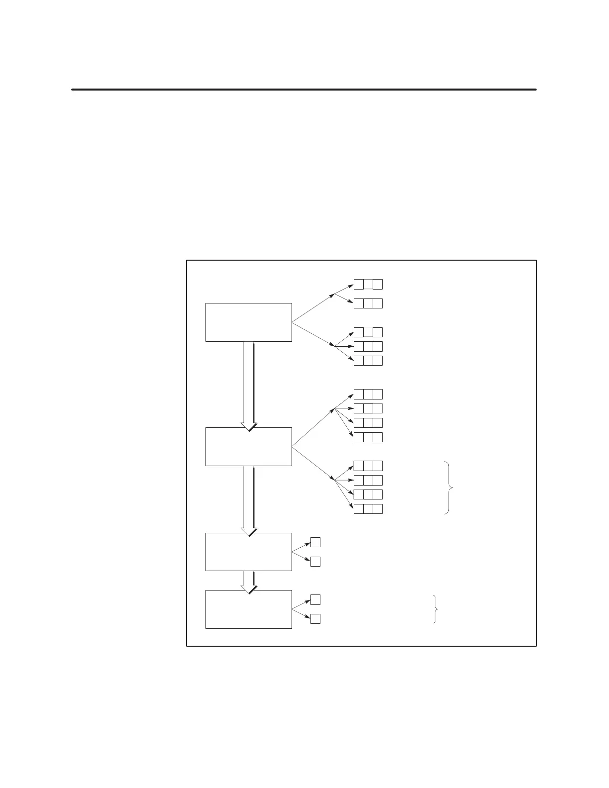
Figure 5-6 is a flowchart representing the options available for the 24-bit
counter by programming the upper 8 bits of WY21 for Counter 1 or the
upper 8 bits of WY27 for Counter 4.
Counter
T
ype
Bits 1, 2, 3
Direction counting
Up/Down counting
0
0
Counter Mode Setup
Bits 4, 5, 6
Divide-by-N counting, non-recycle mode
Internal sample
INDEX
Bit 7
Index or period latches count value
Index or period loads counter with Preset 1 (or Preset 5)
0
1
Output
Bit 8
Compare output, latch, toggle
Rollover output
0
1
0
1
x
x
0
1
Note:
Y
ou must also
set counter output
jumpers to match.
123
0
0
0
1
Binary counting, recycle mode
645
7
8
1X Quadrature
2X Quadrature
1
1
0
0
0
1
123
4X Quadrature
1 1 x
1
1
0
0
45
0
1
6
1 1
0
1 1
1
1 millisecond
10 milliseconds
100 milliseconds
1 second
10 0
Binary counting, non-recycle mode
Divide-by-N counting, recycle mode
0
0 1
Figure 5-6 Flow
of Pr
ogramming Options for 24-Bit Counter
24-Bit Counter
Programming
Options