Using the Default Configurations
4-5
High Speed Counter Encoder Module User Manual
4.3 Basic Programming Steps
To
program the High Speed Counter Encoder module and place it in Run
Mode, perform the following steps:
In your RLL program, write the preset values to the words that correspond
to the counters you are setting up. A preset value of all zeros is valid. As
described in Chapter 3, preset values for each counter are stored in the WY
words listed in T
able 4-2.
Until the module is programmed, the PLC sees the module as
unprogrammed and the green
RUN
LED blinks fast.
T
able 4-2
Wor
d Outputs for Pr
eset V
alues
Word Description Counter
WY21
WY22
WY23
WY24
PRESET 1, high word
PRESET 1, low word
PRESET 2, high word
PRESET 2, low word
Counter 1
WY25
WY26
PRESET 3, word
PRESET 4, word
Counter 2
Counter 3
WY27
WY28
WY29
WY30
PRESET 5, high word
PRESET 5, low word
PRESET 6, high word
PRESET 6, low word
Counter 4
WY31
WY32
PRESET 7, word
PRESET 8, word
Counter 5
Counter 6
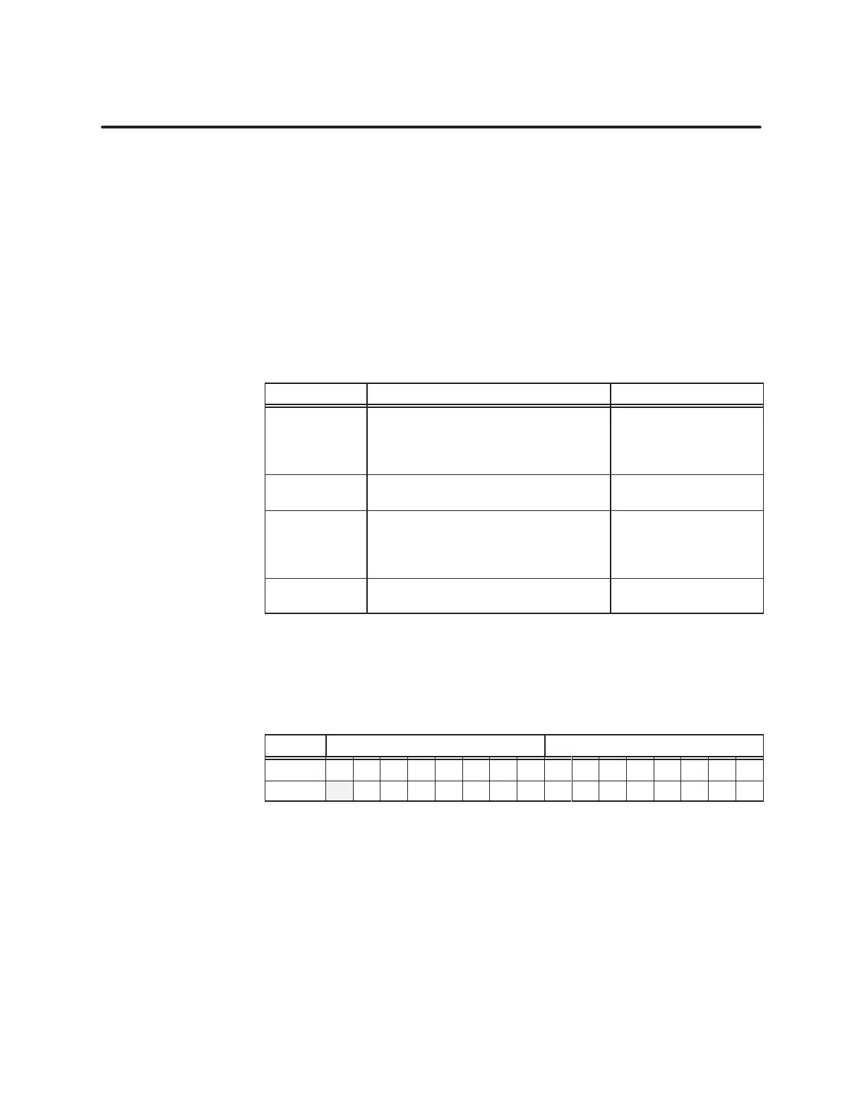
Set
bit WY20.01, shown shaded in T
able 4-3. All other bit values in the
module Setup W
ords WY19 and WY20 can be left at zero.
T
able 4-3
Setting Bit 1 to Pr
ogram the Module
Word MSByte LSByte
WY19 1 2 3 4 5 6 7 8 9 10 11 12 13 14 15 16
WY20 1 2 3 4 5 6 7 8 9 10 11 12 13 14 15 16
When the module detects that WY20.01 is set, it configures the module by
reading the programming bits and preset words in locations WY19 through
WY32. The green
RUN
LED goes off.
Clear bit WY20.01. If no module fault or programming error is detected, the
Run flag, WX18.01 becomes set and the module transitions to Run Mode.
The green
RUN
LED comes on steadily
.
W
riting the Pr
esets
Programming
the Module
Setting RUN Mode