Installing the Module
2-4
High Speed Counter Encoder Module User Manual
2.3 Wiring the Module
You
should wire all of your input and output signals to the HSCE module
removable terminal block. T
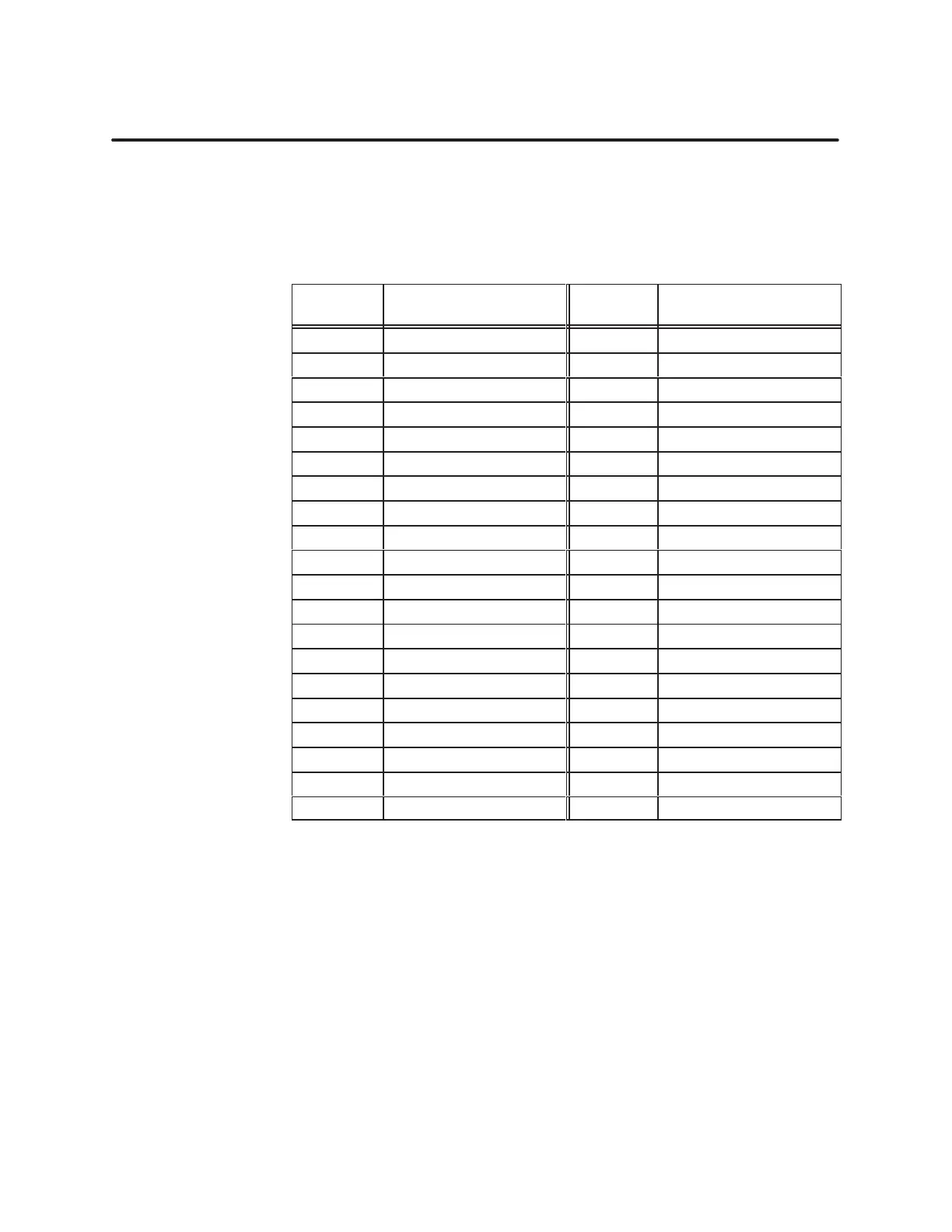
able 2-1 lists the I/O connections together with a
cross-reference listing of the terminals in numeric order
T
able 2-1
I/O Connections
Terminal
Block
Connection Terminal
Block
Connection
AR Back-up Power RTN AC Back-up Power +
A1 Ch1 A– A5 Ch1 A+
A2 Ch1 B– A6 Ch1 B+
A3 Ch1 C– A7 Ch1 C+
A4 Ch1 D– A8 Ch1 D+
BR Ch1 INDEX– BC Ch1 INDEX+
B1 Ch1 RESET– B5 Ch1 RESET+
B2 Ch1 INHIBIT– B6 Ch1 INHIBIT+
B3 Ch2 A– B7 Ch2 A+
B4 Ch2 B– B8 Ch2 B+
CR Ch2 C– CC Ch2 C+
C1 Ch2 D– C5 Ch2 D+
C2 Ch2 INDEX– C6 Ch2 INDEX+
C3 Ch2 RESET– C7 Ch2 RESET+
C4 Ch2 INHIBIT– C8 Ch2 INHIBIT+
DR RTN DC PWR+
D1 Output 2 D5 Output 1
D2 Output 4 D6 Output 3
D3 Output 6 D7 Output 5
D4 Output 8 D8 Output 7
The
outputs are driven by external 24 VDC user
-supplied power
. Figure 2-3
shows the location of the terminals for connecting the 24 V power supply
.
The counters can continue counting, in the event of a power loss to the I/O
base, if you provide 12 VDC back-up power to the module. Figure 2-3 shows
the location of the terminals for connecting the 12 V back-up power
.
I/O Connections
W
iring 24 V User
Power
W
iring 12 V
Back-up Power