Optional Configurations
5-19
High Speed Counter Encoder Module User Manual
T
able 5-10
Bit
Definitions for the Pr
ogram Mode Setup W
ords
Word.Bit Description of Bit Functions for PROGRAM Mode
WY19.01
through
WY19.08
At start of Program Mode, all of the counters are inhibited and reset.
WY20.07
WY20.08
Channel 1, 16-bit Counters 2 and 3: Down (0) or Up (1) counting
Channel 2, 16-bit Counters 5 and 6: Down (0) or Up (1) counting
WY20.09
WY20.10
WY20.11
WY20.12
WY20.13
WY20.14
WY20.15
WY20.16
Channel 1, Counter 2: M
1
Channel 1, Counter 2: M
2
Channel 1, Counter 3: M
1
Channel 1, Counter 3: M
2
Channel 2, Counter 5: M
1
Channel 2, Counter 5: M
2
Channel 2, Counter 6: M
1
Channel 2, Counter 6: M
2
16-Bit Counter Mode of Operation:
M
1
M
2
Description
0 0 Retriggerable one-shot
0 1 Divide-by-N
1 0 Square Wave
1 1 Triggered Strobe
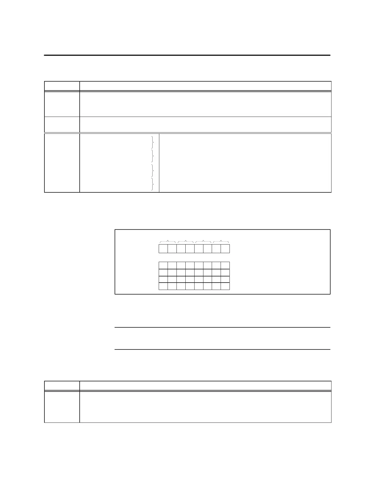
Figure 5-8
is a graphic representation of how to set the bit patterns to
configure the counting mode for each of the 16-bit counters.
16-Bit Counter Mode:
Retriggerable one-shot
Divide-by-N
Square Wave
Triggered Strobe
09 10 11 12 13 14 15 16
00 00 00 00
01 01 01 01
10 10 10 10
11 11 11 11
Counter 2 3 5 6
M
1
M
2
M
1
M
2
M
1
M
2
M
1
M
2
WY20
Figure 5-8 16-Bit
Counter Mode Setup
NOTE:
Chapter 1, Section 1.8 describes the Retriggerable One-shot,
Divide-by-N, Square W
ave, and T
riggered Strobe counter modes in detail.
T
able 5-11
Bit Definitions for the Run Mode Setup W
ords
Word.Bit Description of Bit Functions for RUN Mode
WY19.03
WY19.04
WY19.07
WY19.08
Ch1, Counter 2: Reset Counter; count value is cleared to 0 when set. Reset and Go function.
Ch1, Counter 3: Reset Counter; count value is cleared to 0 when set. Reset and Go function.
Ch2, Counter 5: Reset Counter; count value is cleared to 0 when set. Reset and Go function.
Ch2, Counter 6: Reset Counter; count value is cleared to 0 when set. Reset and Go function.