Installing the Module
2-7
High Speed Counter Encoder Module User Manual
Input
connections to the module can be electronic output drive devices or
mechanical switches.
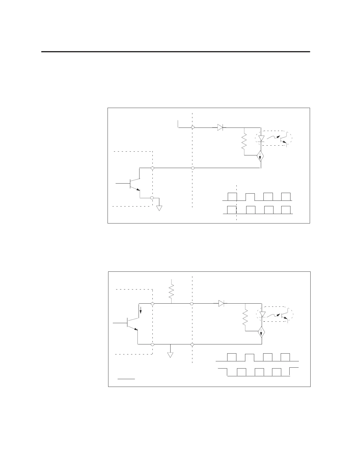
Figure 2-4 shows an example of wiring electronic encoder outputs to the
input terminals of the module for a non-inverted signal.
V
A+
A–
Input
Encoder
Module
OCI
Constant
current
load
Input
OCI
On
Figure 2-4 Non-Inverted
Input Drive
Figure 2-5 shows an example of wiring electronic encoder outputs to the
input terminals of the module for an inverted signal.
V
A+
A–
Input
Encoder
Module
OCI
Constant
current
load
Input
OCI
On
Ic
R=V–4V
13mA
(
Ic
rating
must allow for this current)
Figure 2-5 Inverted
Input Drive
W
iring the Inputs