Installing the Module
2-2
High Speed Counter Encoder Module User Manual
2.1 Overview of Installation
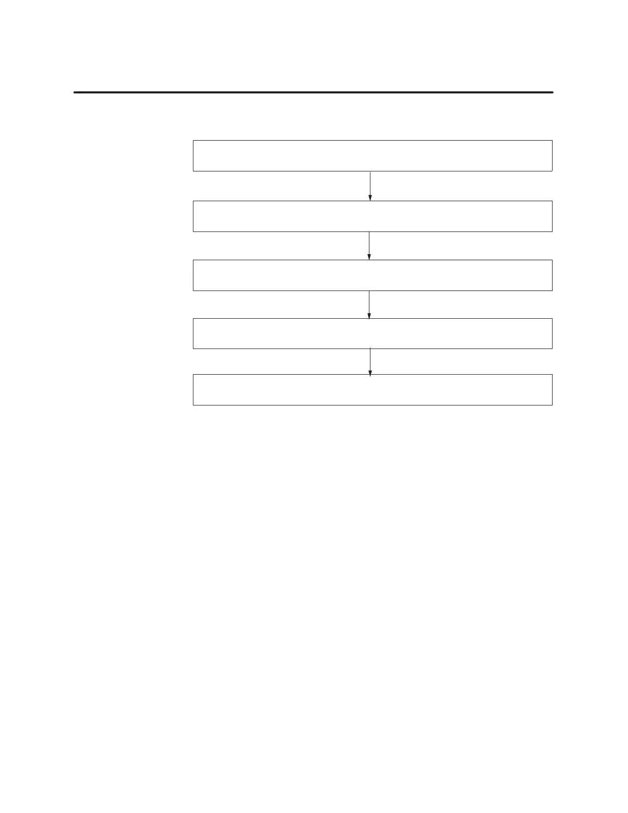
Figure 2-1
shows the flow of tasks to follow when you install this module.
Configure
counter mode of operation (See Chapters 3, 4, and 5.)
Chapter 4 describes the default configuration of the module.
Insert module into I/O base.
Connect I/O wiring to the terminal block.
Power up and check status of LEDs.
Configure I/O address in controller memory
.
Figure 2-1 Flowchart
of Installation
Many integrated circuit (IC) devices are susceptible to damage by the
discharge of static electricity
. Follow the precautions below to reduce the
probability of damage when you are handling the HSCE module, the
controller
, or any of the I/O modules.
T
ake the following precautions to help ensure that you and the module are
at the same ground potential.
• T
ransport the module in an anti-static container or in anti-static
material.
•
Ensure that the work area has a conductive pad with a lead connecting
it to a common ground.
•
Ground yourself by making contact with the conductive pad and/or by
wearing a grounded wrist strap
If there is any visible damage to the module, contact your vendor for
replacement.
Flow of T
asks
Handling the
Module
V
isual Inspection