Understanding Module Operation
3-15
High Speed Counter Encoder Module User Manual
3.7 Setting Preset Values and Programming Options for Channel 2
The
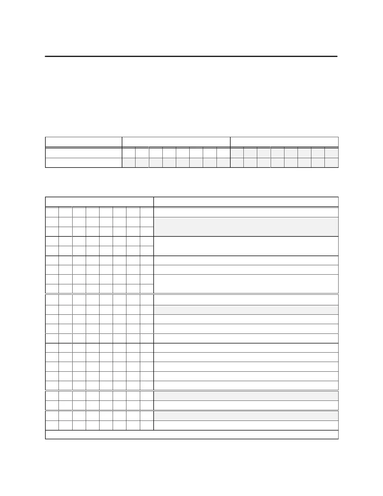
lower byte of WY27 and all of WY28 contain the 24-bit integer Preset 5
value. Use the upper byte of WY27 to configure programming values.
Together
, the preset value and the programmed values determine the count
method and how count Output 5 functions when count and preset are equal,
or when the count value overflows or underflows. T
able 3-16 shows the word
formats, and T
able 3-17 lists the programming values of WY27.
T
able 3-16
Channel 2, 24-Bit Counter: Pr
eset 5 V
alue
Word MSByte LSByte
WY27 1 2 3 4 5 6 7 8 9 10 11 12 13 14 15 16
WY28 1 2 3 4 5 6 7 8 9 10 11 12 13 14 15 16
T
able 3-17
Channel 2, 24-Bit Counter: WY27 Pr
ogramming Bit V
alues
Bit Position Description
01 02 03 04 05 06 07 08 Mode
0 0 0
Direction counting (count: input A, direction: input B)
0 0 1
Direction counting (count: input A, direction: input B)
0 1 0
Up/Down counting (count up: input A, count down: input B)
0 1 1
Up/Down counting (count up: input A, count down: input B)
1 0 0 Quadrature 1X (input A pulses, input B pulses)
1 0 1 Quadrature 2X (input A pulses, input B pulses)
1 1 0
Quadrature 4X (input A pulses, input B pulses)
1 1 1
Quadrature 4X (input A pulses, input B pulses)
01 02 03 04 05 06 07 08 Counter Mode Setup
0 0 0 Binary counting, recycle mode
0 0 1 Binary counting, non-recycle mode*
0 1 0 Divide-by-N counting, recycle mode
0 1 1 Divide-by-N counting, non-recycle mode*
01 02 03 04 05 06 07 08 Internal Sample Interval
1 0 0 1 millisecond sample, (binary, recycle mode)
1 0 1 10 millisecond sample, (binary, recycle mode)
1 1 0 100 millisecond sample, (binary, recycle mode)
1 1 1 1 second sample, (binary, recycle mode)
0 Index or Period pulse latches counter value
1 Index or Period pulse loads counter with preset 5 value
0 Output Compare, Latch, Compare Toggle, (select jumper to match)
1 Output Rollover, (select jumper to match)
*In this mode, the output is configured as borrow toggle and carry toggle. These outputs are the cycle completion indicator.
Channel
2,
24-Bit Counter 4,
Pr
eset 5