Product Overview
1-23
High Speed Counter Encoder Module User Manual
For
an odd preset value, the preset – 1 value is loaded, and the counter
starts decrementing by two after the first clock pulse. The output turns On
when the count value is zero and would underflow
, however
, the counter
automatically reloads the preset + 1 value into the counter and starts
decrementing by two.
The output turns Off when the count value is zero again. The counter
automatically reloads the preset – 1 value into the counter and starts
decrementing by two.
This cycle repeats until a high gate control signal pauses the counting. A
gate can be an external input or the PLC can set the Reset Counter flags,
WY19.03, .04, .07, or .08 corresponding to counters 2, 3, 5, or 6. When the
gate goes On, the counting pauses and the outputs turn Off. When the gate
is released (turns Off) or the Reset Counter flag is cleared, the counter is
loaded with the preset value, and counting resumes on the next valid clock.
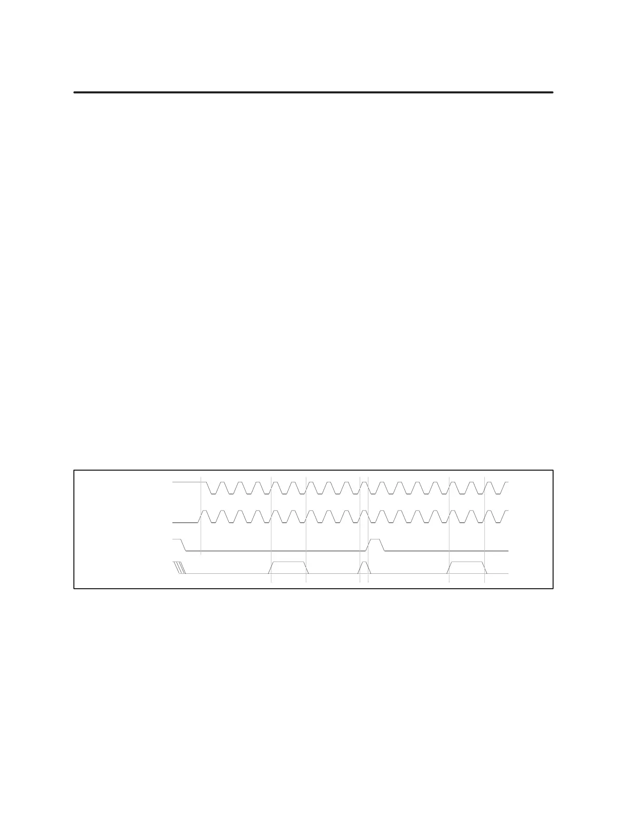
The square-wave generator waveform, Figure 1-17, shows that for an odd
initial preset value of five, the output is Off and remains Off until the
counter decrements to one-half the initial value. When the counter counts
the preset value down (three clocks Off and two clocks On), the output goes
On for the other half of the initial count. The gate input Off enables the
counter; On inhibits the counter
.
For an odd initial preset value, the output is On for ((N+1) / 2) counts and
Off for ((N–1) / 2) counts. An initial count of five results in the waveform
shown in Figure 1-17.
Pulse
Input
Starts Of
f
Gate, Reset, or
Programming
Output
Starts On
20 4 2 0 4 2 4 2 0 420 4 4 2 0 4 242
20 4 2 0 4 2 4 2 0 419 4 4 2 0 4 2 4 2
Figure 1-17 Square-Wave
Generator (Odd Pr
eset V
alue)
Squar
e W
ave
Generator Odd
Pr
eset V
alue