Product Overview
1-9
High Speed Counter Encoder Module User Manual
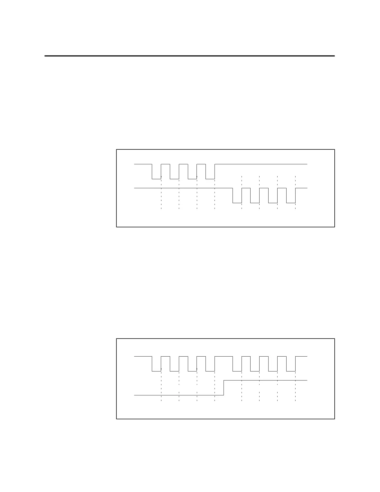
1.4 Non-Quadrature Modes of Counting
When
you select the up/down counting mode, two input pulse signals
determine the count value. (Refer to Figure 1-7.)
• W
ith input B high, the count increments on the rising edge of input A.
• W
ith input A high, the count decrements on the rising edge of input B.
For proper counting, the input without the clock must be held high or on;
otherwise, the count value that results cannot be defined.
A
5678Count
V
alue: 74
B
56
Up Count
Down Count
Up/Down Pulse Counting Mode
Figure 1-7 Up/Down
Counting
When you select direction counting mode, the input B signal controls the
count values of the input A pulse. (Refer to Figure 1-8.)
• W
ith input B low
, the count increments on the rising edge of input A.
• W
ith input B high, the count decrements on the rising edge of input A.
For proper counting, input A must be high during the transition of input B;
otherwise, the count value that results can not be defined.
A
4321Count
V
alue: 25
B
43
Up/Down Direction Counting Mode
Down Counting
Up Counting
Figure 1-8 Direction
Counting
Up/Down Counting
Overview
Dir
ection Counting
Overview

 Loading...


