Optional Configurations
5-16
High Speed Counter Encoder Module User Manual
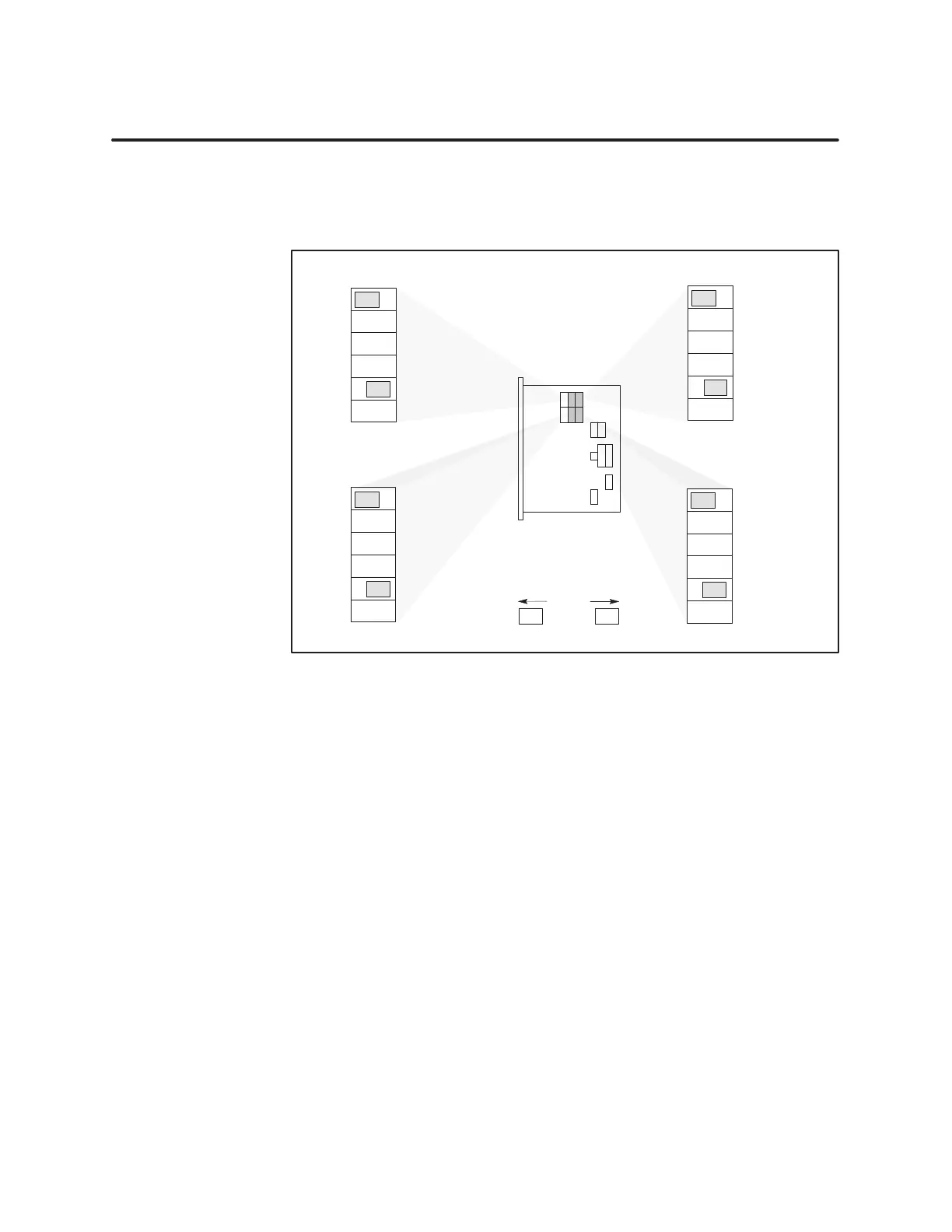
5.8 16-Bit Counter Options
Five
two-position jumpers enable you to select a clock input and control
signal for each 16-bit counter. See Figure 5-7. Jumpers are shown in their
default positions.
Jumper
Holding
1
µs clock
A Input Pulse
B Input Pulse
C Input Pulse
Counter 3 Output
Counter 2
•••
•••
•••
•••
•••
E13
E14
E15
E16
E17
E18
Jumper
Holding
1
µs clock
A Input Pulse
B Input Pulse
D Input Pulse
Counter 2 Output
Counter 3
E25
E26
E27
E28
E29
E30
Jumper Holding
1
µs clock
A Input Pulse
B Input Pulse
C Input Pulse
Counter 6 Output
Counter 5
Jumper Holding
1
µs clock
A Input Pulse
B Input Pulse
D Input Pulse
Counter 5 Output
Counter 6
E19
E20
E21
E22
E23
E24
E31
E32
E33
E34
E35
E36
Gate/Trigger Clock/Pulse
••••••
16-Bit
Counter
jumper positions
•••
•••
•••
•••
•••
•••
•••
•••
•••
•••
•••
•••
•••
•••
•••
•••
•••
•••
•••
Figure 5-7
16-Bit Counter Jumpers
After you select the jumpers, you must program the setup words and preset
words to enable the selected functions.