Specifications
C-5
High Speed Counter Encoder Module User Manual
The
input filter has a clock that synchronizes the input pulse train. The
clock periods for each filter are listed below
.
Filter Frequency 1/2 Filter Period
100 kHz filter: 2 microseconds
25 kHz filter:
8 microseconds
6.25 kHz filter:
32 microseconds
1.5 kHz filter:
128 microseconds
400 Hz filter:
512 microseconds
100 Hz filter:
2048 microseconds
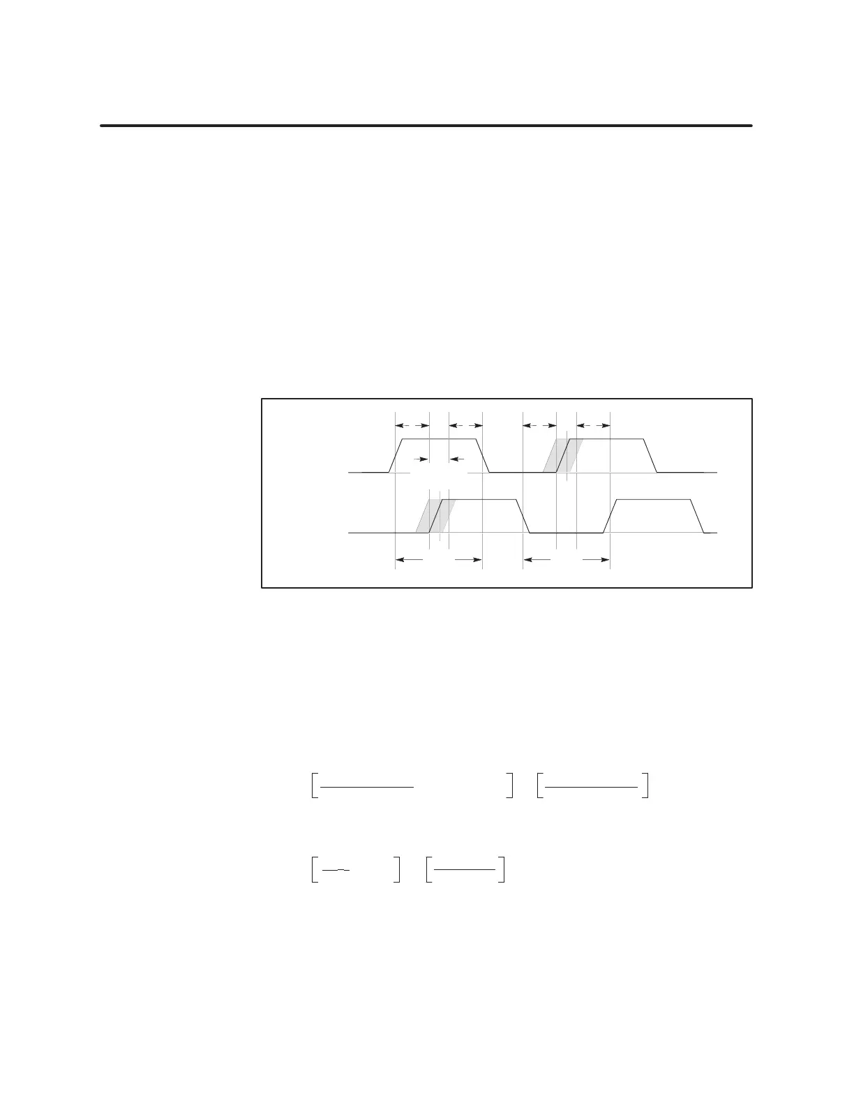
To
properly register the counting edges, the edges must be separated by at
least these times. This is demonstrated in Figure C-4 with a 100 kHz
Quadrature signal.
Input
Signal A
Input Signal B
2
s
2
s
2
s
2
s
±18°
(±
0.5
s)
5
s
5
s
Figur
e C-4
Pulse
W
idth Requirements for Quadratur
e Filtering at 100 kHz
The period of a 100 kHz signal is 10 microseconds (
s). A 90 degree phase
shift between two 100 kHz signals is 2.5
s, edge to edge. The filter period is
2
s. Therefore, the signals can be
±
0.5
s off of a 90 degree phase shift, and
still count properly
.
T
o calculate phase shift, use the following formula:
Signal
Pulse Width
4
–
1/2 filter period
±
360 degrees
Signal Pulse Width
×
In
the example above, the phase shift is calculated as follows:
10
s
4
–
2
s
±
360 degrees
10
s
×
±
0.5
s × 36°/s ±
18 degrees
Therefore,
an offset of 0.5
s produces a phase shift of
±
18 degrees.
Minimum Pulse
W
idth for
Quadratur
e Mode

 Loading...


