6
6.4 Input/output terminals of the control board
6-504
Siemens AG 2005 All Rights Reserved
SIMODRIVE 611 universal Description of Functions (FBU) – 04.05 Edition
Table 6-49 List of output signals
Operating
mode
Signal name, description Fct. No. n–set pos PROFIBUS bit
Inactive 0 x x –
An output with this function is ”disabled”, i.e. a signal is not output (continuously 0 V).
The output terminal can still be connected–up, but it is not evaluated.
Application:
To start–up a drive (commission a drive) the ”disturbing outputs” are first switched–out, and then are sub-
sequently activated to be commissioned.
| n
act
| < n
min
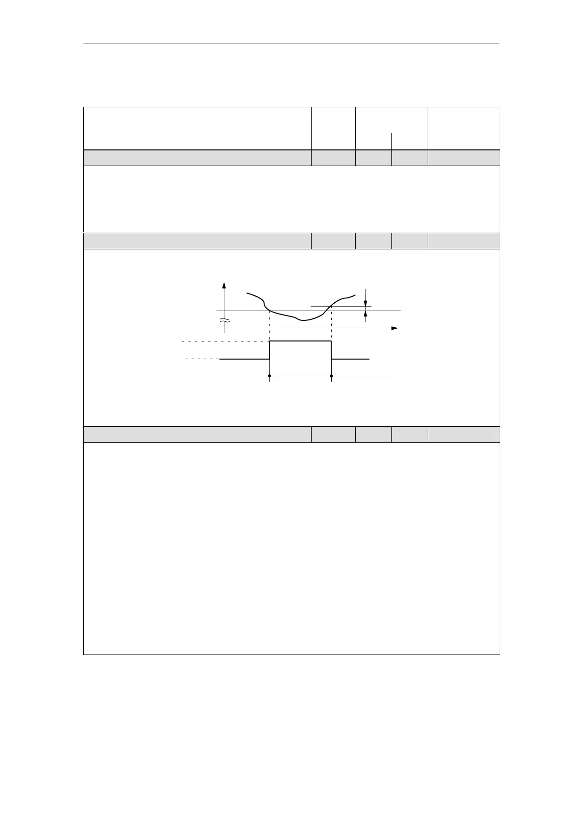
1 x x MeldW.2
This output signal is used to display whether the absolute actual speed (| n
act
|) is less than or greater
than the selected threshold speed (n
min
, P1418:8).
n
min
n
min
(P1418:8)
t
1 signal
0 signal
| n
act
|
| n
act
| < n
min
| n
act
| > n
min
| n
act
| > n
min
n
act
| < n
min
Fixed hysteresis= 2 RPM
Application:
The gearbox stage is only mechanically changed–over if the speed is less than that set in P1418:8, in
order to reduce the stressing on the mechanical system.
Ramp–up completed 2 x x MeldW.0
The end of a ramp–up operation is displayed after the speed setpoint has been changed, using this out-
put signal.
1 signal Ramp–up has been completed
1/0 signal Ramp–up starts
The start–up is identified, if
– the speed setpoint changes
and
– the defined tolerance bandwidth (P1426) is exited.
0 signal Ramp–up runs
0/1 signal Ramp–up has been completed
The end of ramp–up is identified, if
– the speed setpoint is constant
and
– the speed actual value is within the tolerance bandwidth around the speed setpoint
and
– the delay time has expired (P1427).
Note:
Detailed information on the ramp–function generator is provided in Chapter 6.1.3.
6 Description of the Functions
08.01