6
6.6 Analog inputs
6-538
Siemens AG 2005 All Rights Reserved
SIMODRIVE 611 universal Description of Functions (FBU) – 04.05 Edition
The following parameters are available to parameterize the M
red
mode
using terminal 24.x/20.x:
Table 6-54 Parameter for the M
red
mode
Parameters
No. Description Min. Stan-
dard
Max. Units Effec-
tive
0611 Voltage at terminals 24.x/20.x – – – V(pk) RO
0613 Inversion terminal 24.x/20.x 0 0 1 – Imme-
diately
For the torque/power reduction, internally only positive setpoints are effective. For a negative
analog setpoint at terminal 24.x/20.x, an inversion function must be switched–in.
0614 Smoothing time, terminal 24.x/20.x (SRM,
SLM)
(ARM)
0.0
0.0
3.0
1 000.0 ms
Imme-
diately
0615 Drift/offset correction terminal 24.x/20.x –9 999.9 0.0 9 999.9 mV(pk) Imme-
diately
Note:
These parameters are described in Chapter 6.6.3.
0620 Normalization voltage, torque/power reduc-
tion (SRM, ARM)
Normalization voltage, force/power reduction
(SLM)
5.0 10.0 12.5 V(pk)
Imme-
diately
1243:8 Normalization, torque/power reduction
(SRM, ARM)
Normalization, force/power reduction (SLM)
0.0 100.0 100.0 %
Imme-
diately
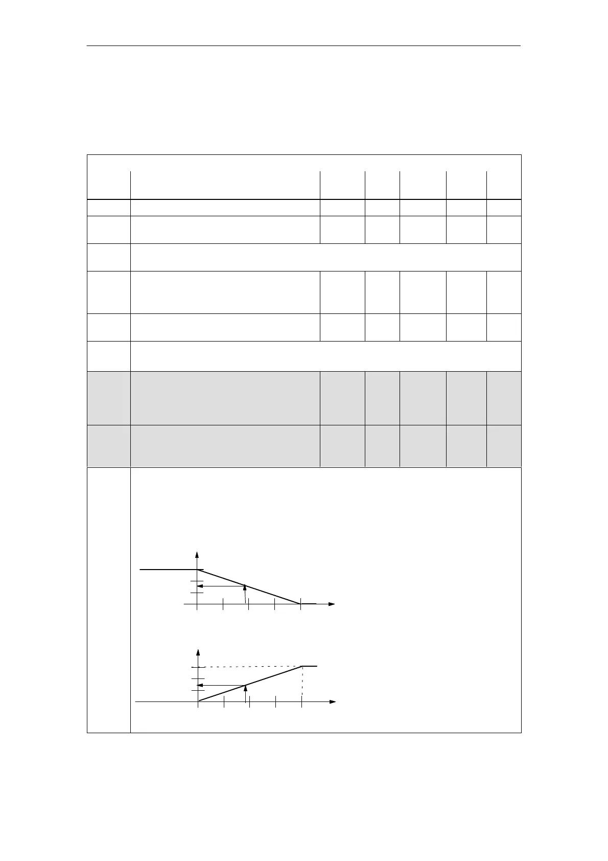
P0620: ... defines up to which maximum voltage, a reduction can be made.
P1243:8 ... defines up to which maximum torque or power a reduction can be made.
The data is a percentage with the following reference:
Reference for torque: P1230 (1st torque limit)
Reference for power: P1235 (1st power limit)
M
effective
/P
effective
[%]
M
max/
P
max
10 V
V
Red
[V]
Example:
P1244 = 1 (neg. characteristic)
P0620 = 5 V
P1243 = 50 %
––>
with an input voltage
of 0 V to 5 V, the
torque/power can be
reduced from
50 % to 0 %, referred to
P1230/P1235
Note:
The actual reduction is displayed
in P1717.
0 V
M
effective
/P
effective
[%]
M
max/
P
max
V
Red
[V]
P1243
P1243
P0620
P0620
10 V0 V
P1244 = 1
P1244 = 2
Parameter
overview
6 Description of the Functions
10.99
 Loading...


