7
7.4 Commissioning functions
7-726
Siemens AG 2005 All Rights Reserved
SIMODRIVE 611 universal Description of Functions (FBU) – 04.05 Edition
7.4.4 Measurement function
Using the measuring function, by using simple parameterization, the
influence of higher–level control circuits can be disabled and the dyna-
mic performance of the individual drives can be displayed without using
any external measuring equipment.
This means that it is possible to evaluate and analyze important quanti-
ties of the current and speed control loop in the time and frequency do-
mains.
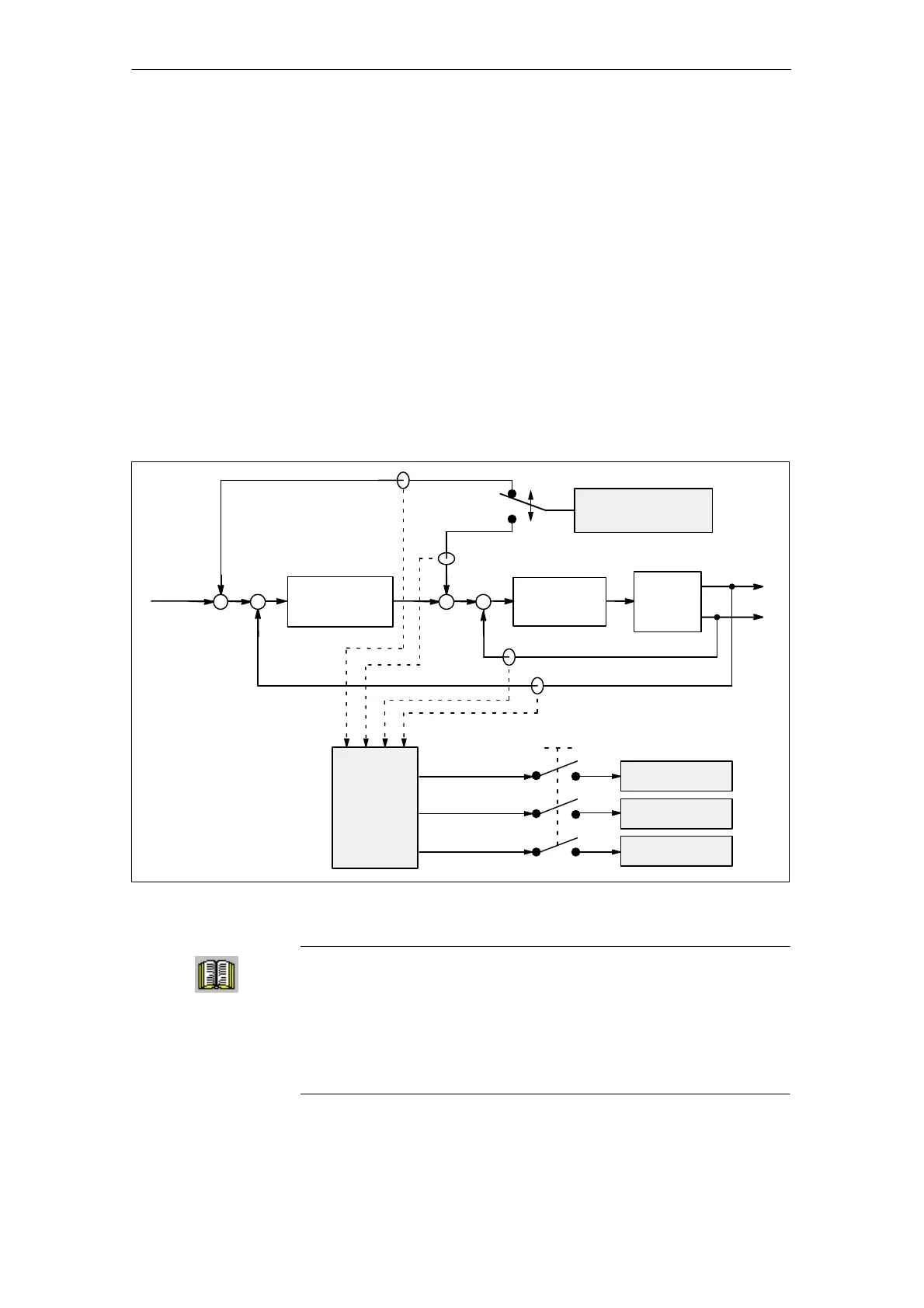
Test signals with a selectable time interval are input into the drives to
determine the measured values for graphic display of the time and fre-
quency characteristics of drives and closed–loop control functions.
Test signal
generator
–
–
Test duration (T
test
)
Meas.
value
selection
(max. 3)
Meas. value 1
Meas. value 2
Meas. value 3
Speed setpoint
Current
setpoint
Actual current value
Speed actual value
Setpoint
0
Speed
controller
Current
regulator
Control
loop
Meas. buffer 2
Meas. buffer 3
Meas. buffer 1
Fig. 7-11 Block diagram of the drive optimization (schematic)
Reader’s note
The trace function can only be used together with the SimoCom U
parameterizing and start–up tool, i.e. SimoCom U is used to control
the trace function and to display the measured values.
Additional information on the measuring functions is provided in the
online help for SimoCom U.
Overview
Measuring
principle
7 Fault Handling/Diagnostics