2
2.3 Connection diagram and wiring
2-73
Siemens AG 2005 All Rights Reserved
SIMODRIVE 611 universal Description of Functions (FBU) – 04.05 Edition
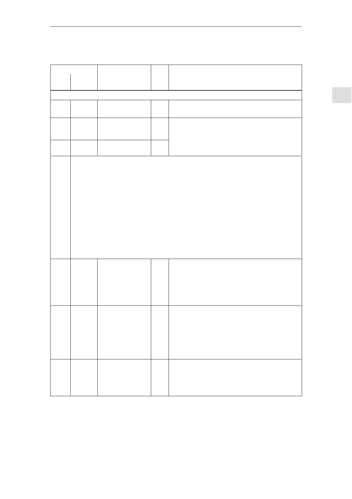
Table 2-3 Overview of the board–specific terminals and interfaces, continued
Terminals Technical dataType
1)
Function
No.
Technical dataType
1)
Function
Desig-
nation
Terminals for supply and pulse enable (X431)
X431
Connector type: 5–pin conn. strip
Max. cond. cross–sect.: 1.5 mm
2
P24 X431.1 External power sup-
ply for digital outputs
(+24 V)
S
Voltage tolerance
(including ripple): 10 V to 30 V
M24 X431.2 Reference for the
external supply
S
(including ripple): 10 V to 30 V
The external supply is required for the following digital outputs:
8 outputs of the drive–specific terminals (X461, O0.A – O3.A/X462, O0.B – O3.B)
8 outputs of the optional TERMINAL module (X432, O4 – O11)
When dimensioning the external power supply, the total current of all of the digital outputs must
be taken into account.
Maximum total current:
for the control board (all 8 outputs): 2.4 A
for the optional TERMINAL module (all 8 outputs): 480 mA
Example:
Board/module Outputs Dimensioning the external supply
Control board 8 max. 1.5 A ––> 24 V/1.5 A
Control module +
optional TERMINAL module 8 + 8 max. (1.5 A + 280 mA) ––> 24 V/1.8 A
9 X431.3 Enable voltage
(+24 V)
S Reference: Terminal 19
Maximum current (for the total group): 500 mA
Note:
The enable voltage (terminal 9) can be used to supply
the enable signals (e.g. pulse enable) as 24 V auxil-
iary voltage.
663 X431.4 Pulse enable
(+24 V)
I Voltage tolerance
(including ripple): 21 V to 30 V
Typ. curr. consumption: 25 mA at 24 V
Note:
The pulse enable acts simultaneously on drive A and
drive B. When this pulse enable is withdrawn, the
drives ”coast down” unbraked.
19 X431.5 Reference
(Reference for all
digital inputs)
S Note:
If the enable signals are to be controlled from an exter-
nal voltage and not from terminal 9, then the reference
potential (ground) of the external source must be con-
nected to this terminal.
1) I: Input; S: Supply
2 Installing and Connecting-Up