2
2.3 Connection diagram and wiring
2-74
Siemens AG 2005 All Rights Reserved
SIMODRIVE 611 universal Description of Functions (FBU) – 04.05 Edition
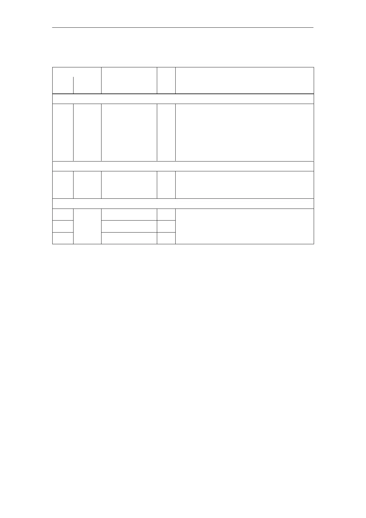
Table 2-3 Overview of the board–specific terminals and interfaces, continued
Terminals Technical dataType
1)
Function
No.
Technical dataType
1)
Function
Desig-
nation
Serial interface (X471)
– X471 Serial interface for
”SimoCom U”
IO Connector type: 9–pin D–sub socket connector
Note:
Online operation via the serial RS232/RS485 inter-
face ––> refer to Chapter 3.3.3
Pin assignment of the interface ––> refer to Chap-
ter 2.4
Cable diagram ––> refer to Chapter 2.5
Equipment bus (X351)
– X351 Equipment bus IO Ribbon cable: 34–pin
Voltages: various
Signals: various
Test sockets (X34)
DAU1 Test socket 1
2)
MA Test socket: ∅ 2 mm
DAU2
X34
Test socket 2
2)
MA
Resolution: 8 bit
Voltage range: 0 V to 5 V
M Reference MA
Voltage range: 0 V to 5 V
Maximum current: 3 mA
1) IO: Input/output; MA: Measuring signal, analog
2) Can be freely parameterized
2 Installing and Connecting-Up
10.99