A
A.2 Power module list
A-856
Siemens AG 2005 All Rights Reserved
SIMODRIVE 611 universal Description of Functions (FBU) – 04.05 Edition
A.2 Power module list
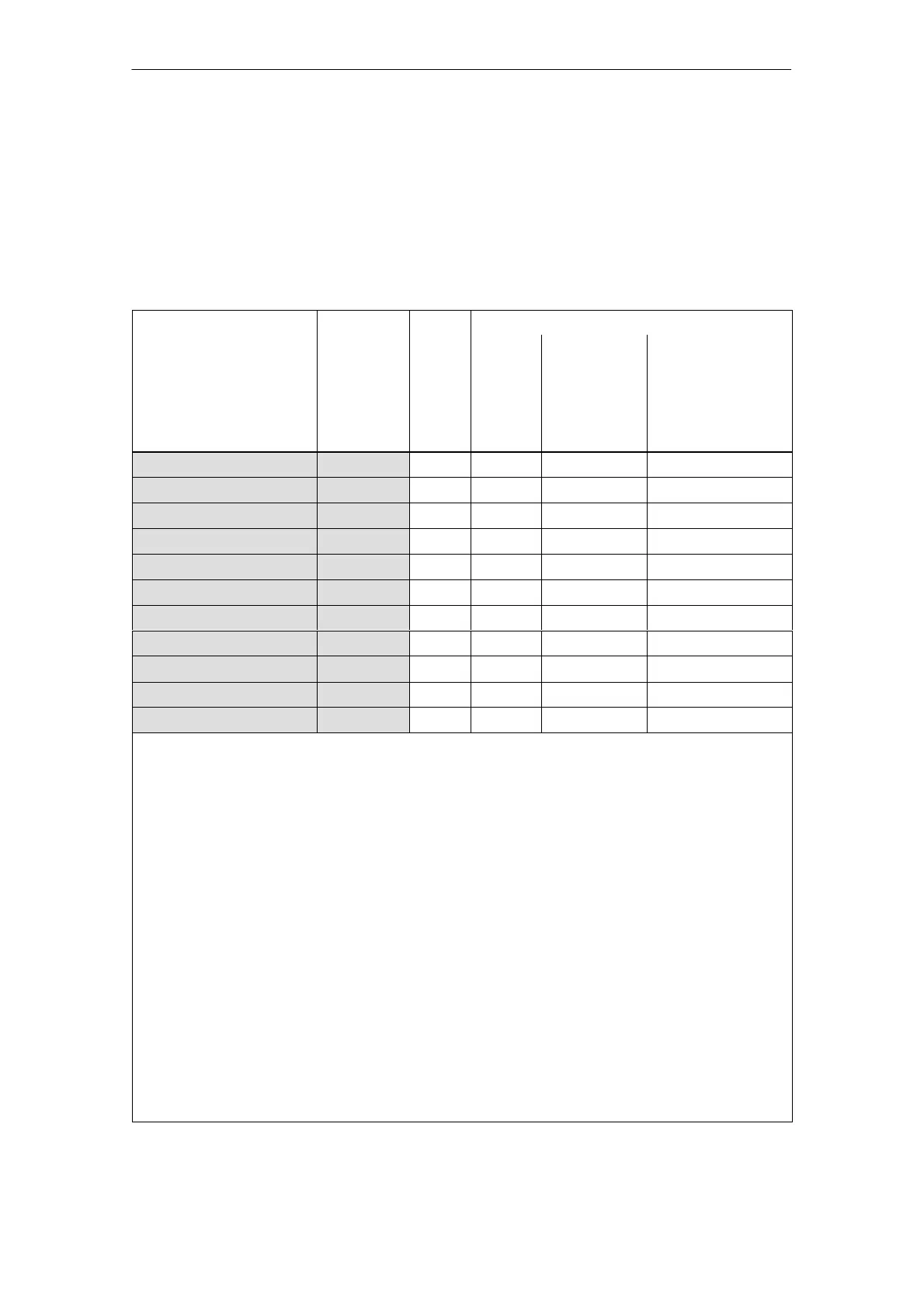
A power module is defined by its Order No. (MLFB) and internally by its
code number.
Table A-1 Power module Order No. and code
Order No.
Power mod
No. of
Current rating
Tran–
sistor
current
Motor
1)
1FT6, 1FK6,
1FNx
Motor
1)
1PHx,
1FE1 (from SW 3.1)
P1106 [A(pk)]
P1107
I
n
/I
max
[A(rms)]
P1111/P1108
I
n
/I
S6
/I
max
[A(rms)]
P1111/P1109/P1108
6SN112x–1Ax0x–0HAx 1 1/2 8 3/6 3/3/3
6SN112x–1Ax0x–0AAx 2 1/2 15 5/10 5/5/8
6SN112x–1Ax0x–0BAx 4 1/2 25 9/18 8/10/16
6SN112x–1Ax0x–0CAx 6 1/2 50 18/36 24/32/32
6SN112x–1Ax0x–0DAx 7 1 80 28/56 30/40/51
6SN112x–1Ax0x–0LAx 13
2)
1 108 42/64 45/60/76
6SN112x–1Ax0x–0GAx 8
2)
1 120 42/64 45/60/76
6SN112x–1Ax0x–0EAx 9 1 160 56/112 60/80/102
6SN112x–1Ax0x–0FAx 10 1 200 70/140 85/110/127
6SN112x–1Ax0x–0JAx 11
2)
1 300 100/100 120/150/193
6SN112x–1Ax0x–0KAx 12 1 400 140/210 200/250/257
Note:
rms: rms value
pk: Peak value
x: Space retainer for the Order No.
I
n
: Continuous current
I
S6
: Current for max. 4 min. for S6 load duty cycle
I
max
: Peak current
1) At higher pulse frequencies (P1100) I
n
, I
max
and I
S6
must be reduced to protect the power
module.
The following applies before SW 2.4:
The display using P1108, P1109 and P1111 depends on the pulse frequency.
The reduction factor is already calculated into this parameter.
The displayed values only correspond to the values in the table for the standard setting of the
pulse frequency (P1100).
The following applies from SW 2.4:
The display using P1108, P1109 and P1111 corresponds to the values in this table.
The limiting factor is displayed in P1099 (limiting factor, power module currents).
Example:
P1111 = 9 A, P1099 = 80 % ––> reduced rated current I
n
= 9 A 80 % = 7.2 A
2) from SW 8.2 onwards (only for PE spindles)
Power module
Order No. and
code
05.0004.05