Configuration
5.3 Examples
1FW6 Built-in torque motors
112 Configuration Manual, 07/2017, 6SN1197-0AE00-0BP9
Table 5- 2 Functions of the individual sections in the traversing profile
ω
I
(t) = α t ω
II
(t) = - α t + α t
1
I
2
II
2
1
MAX
The angular acceleration α (t) is constant section by section. In the first section, the angular
velocity ω (t) increases linearly up to the maximum value, and then in the second section,
linearly down to standstill.
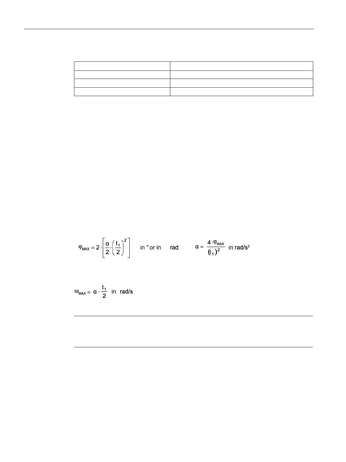
The angle of rotation φ (t) increases in section I and in section II according to parabolic
functions. This type of traversing profile allows the shortest positioning times.
The required constant angular acceleration or angular deceleration can be calculated from
the defined final angle φ
MAX
and the associated instant in time t
1
. For the sake of simplicity,
momentary transitional phases between acceleration/deceleration and the resulting angle
changes are not taken into account.
Since the areas below the curves for ω (t) are the same in both sections, the following
applies:
The angular velocity ½ t
1
reached at instant ω
MAX
is determined from the calculated angular
acceleration:
The speed n
MAX
can be calculated from the n
MAX
= ω
MAX
• 60 / 2π.
Note
1 rad corresponds to
180°/π = 57.296°
1 revolution corresponds to 360° or 2 π rad
The following can be calculated with the values specified:
Angular acceleration α = 52.36 rad/s
2
Angular velocity ω
MAX
= 10.47 rad/s
Speed n
MAX
= 100 rpm

 Loading...


