Safety Integrated Basic Functions
10.9 Control via TM54F
Drive functions
Function Manual, 11/2017, 6SL3097-4AB00-0BP5
707
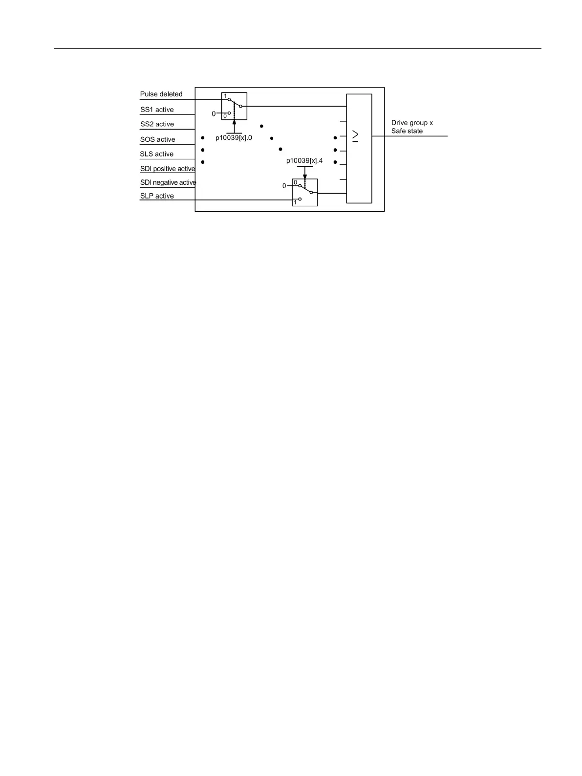
Figure 10-5 Selecting the safe state (example, Extended Functions)
The same signals (high-active) of each drive or drive group are logically linked by means of
AND operation. The different signals selected via p10039 are logically OR'ed. Result of
these logic operations is the "Safe State" for each drive group. You can find details in the
SINAMICS S120/S150 List Manual in function diagrams 2901 (Basic Functions) or 2906
(Extended Functions).
Each F-DO supports the interconnection of up to 6 signals by way of indexing (p10042[0...5]
to p10045[0...5]) and their output as logical AND operation.
Function diagrams (see SINAMICS S120/S150 List Manual)
2893
- fail-safe digital inputs (F-DI 0 … F-DI 4)
2894
- fail-safe digital inputs (F-DI 5 … F-DI 9)
2895
- fail-safe digital outputs (F-DO 0 ... F-DO 3),
digital inputs (DI 20 ... 23)
2900
- Basic Functions control interface
(p9601.2/3 = 0 & p9601.6 = 1)
2901
- Basic Functions Safe State selection
2902
- Basic Functions assignment (F-DO 0 ... F-DO 3)
2905
- Extended Functions control interface
(p9601.2 = 1 & p9601.3 = 0)
2906
- Extended Functions Safe State selection
2907
- Extended Functions assignment (F-DO 0 ... F-DO 3)

 Loading...


