Transformations
6.2 Three, four and five axis transformation (TRAORI)
Job planning
Programming Manual, 07/2010, 6FC5398-2BP40-0BA0
319
In this example, A' lies below the angle φ to the X axis.
The following possible relations are generally valid:
A' lies below the angle φ to the X axis
B' lies below the angle φ to the Y axis
C' lies below the angle φ to the Z axis
Angle φ can be configured in the range 0° to +89° using machine data.
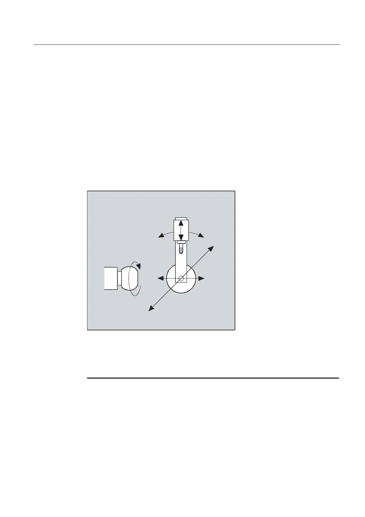
With swiveling linear axis
This is an arrangement with a moving workpiece and a moving tool. The kinematics consists
of three linear axes (X, Y, Z) and two orthogonally arranged rotary axes. The first rotary axis
is moved, for example, over a compound slide of two linear axes, the tool standing parallel to
the third linear axis. The second rotary axis turns the workpiece. The third linear axis (swivel
axis) lies in the compound slide plane.
%
$
=
<
;
The axis sequence of the rotary axes and the orientation direction of the tool can be set up
using the machine data as appropriate for the machine kinematics.
There are the following possible relationships:
Axes: Axis sequences:
1st rotary axis A A B B C C
2nd rotary axis B C A C A B
Swiveled linear axis Z Y Z X Y X
For more detailed information about configurable axis sequences for the orientation direction
of the tool, see
References: /FB3/ Function Manual, Special Functions; 3- to 5-Axis Transformations (F2),
Universal Milling Head section, "Parameter Setting".

 Loading...


