Tool offsets
7.8 Tool holder kinematics
Job planning
436 Programming Manual, 07/2010, 6FC5398-2BP40-0BA0
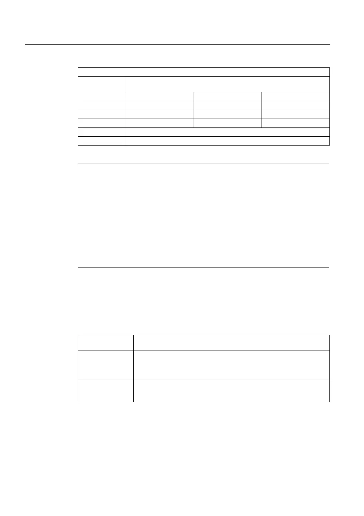
Extensions of the system variables for orientable toolholders
Fine
offset
Parameters that can be added to the values
in the basic parameters.
l
1
Offset vector $TC_CARR41[m] $TC_CARR42[m] $TC_CARR43[m]
l
2
Offset vector $TC_CARR44[m] $TC_CARR45[m] $TC_CARR46[m]
l
3
Offset vector $TC_CARR55[m] $TC_CARR56[m] $TC_CARR57[m]
l
4
Offset vector $TC_CARR58[m] $TC_CARR59[m] $TC_CARR60[m]
v
1
rotary axis $TC_CARR64[m]
v
2
rotary axis $TC_CARR65[m]
Note
Explanations of parameters
"m" specifies the number of the toolholder to be programmed.
$TC_CARR47 to $TC_CARR54 and $TC_CARR61 to $TC_CARR63 are not defined and produce an
alarm if read or write access is attempted.
The start/endpoints of the distance vectors on the axes can be freely selected. The rotation
angles
α
1
, α
2
about the two axes are defined in the initial state of the toolholder by 0°. In this
way, the kinematics of a toolholder can be programmed for any number of possibilities.
Toolholders with only one or no rotary axis at all can be described by setting the direction
vectors of one or both rotary axes to zero.
With a toolholder without rotary axis the distance vectors act as additional tool compensa-
tions whose components cannot be affected by a change of machining plane (
G17 to G19).
Parameter extensions
Parameters of the rotary axes
The system variables have been extended by the entries $TC_CARR24[m] to
$TC_CARR33[m] and described as follows:
Offset of
rotary axes v
1
, v
2
Changing the position of the rotary axis v
1
or v
2
for the initial setting of the
oriented toolholder.
The angle
offset/angle
increment of the
rotary axes v
1
, v
2
The offset or the angle increment of the Hirth tooth system of the rotary axes
v
1
and v
2
. Programmed or calculated angle is rounded up to the next value
that results from phi = s + n * d when n is an integer.
The minimum and
maximum position of
the rotary axes v
1
, v
2
The minimum and maximum position of the rotary axis limit angle (software
limit) of the rotary axes v1 and v2.
Parameters for the user
$TC_CARR34 to $TC_CARR40 contain parameters that are freely available to users and up
to SW 6.4 were as standard, not further evaluated within the NCK or had no significance.

 Loading...


