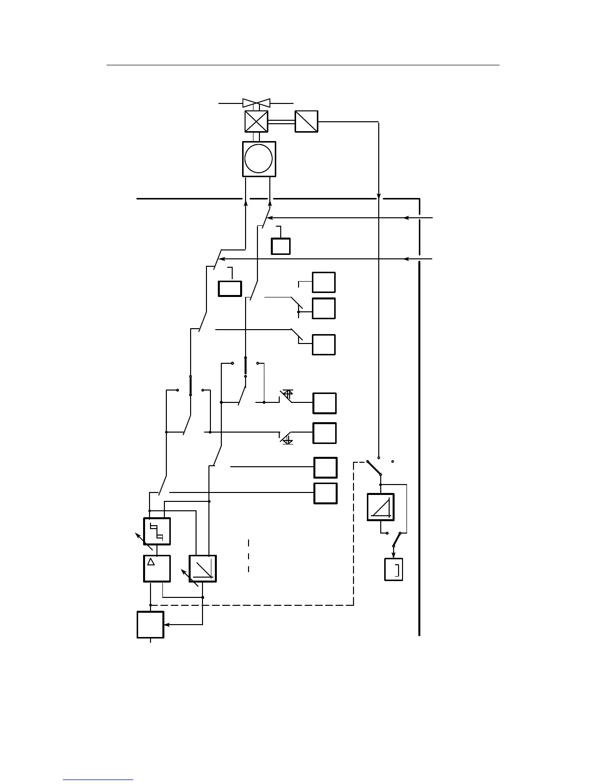
3 Functional description of the structure switches
3.6 Controller output structures (S2, S49 to S55)
Manual
SIPART DR21
C73000-B7476-C143-08
101
0
1
0
2/3
S54
1
S55
2
S51
0
0
00
1
A
2
S51
1
H
+
Δy
H
-Δy
H
N
N
Si
Si
+
-
+
-
tP, tM
tA, tE
internal position control circuit
+
ΔY
a
A
-
ΔY
a
H
+Y
BL
yn
ya
0/(3/4)*
S29
* as of software version –A5
0/(3/4)*
0
S30
-
Δy
y
R
+Δy
S19
S57
S57
μ
E
y
GND
PID
00
Y
An
y
S
>50
y
S
≤50
A=H
∧N∧Si
H=Hi∨He
+yBL -yBL
01
1 1
-yBL
Figure 3-26 Block diagram
S-controller with internal feedback S2 =2
Manual operation has priority over tracking (DDC) S49 = 1