2 Technical Description
2.4 Design
Manual
SIPART DR21
C73000-B7476-C143-08
25
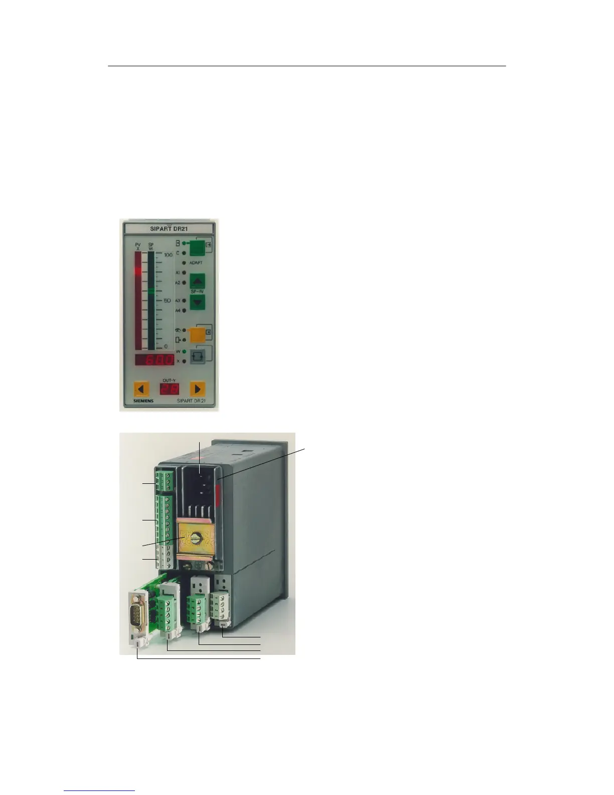
D Connection technique
The power supply is connected
- for 230 V/115 V AC by a three-pin plug
- for 24 V UC by a special two-pin plug.
On the standard controller the field lines (signal cables) are connected to three functionally
combined plug-in screw-type terminals.
The options modules for analog inputs and digital inputs- and outputs have their own ter-
minals which are also designed as plug-in screw-type terminals.
The interface module is connected by its own plug.
Figure 2-1 Front view
1 Mains plug
2 Power supply unit
3 Slot1 AI3(I/U,R,P,T)
4 Slot2 AI4(I/U,R,P,T)
5 Slot 3 4DO,24 V or
2DO relay or
5DI
6 Slot 4 SES/PROFIBUS-DP
7DINrail
(scope of delivery of the relay module)
8 Terminal block 1
AI1toAI2(I)
9 Terminal block 2
AO1
DI1toDI2
DO1toDO2 24V
L+; M
10 Terminal block 3
Digital outputs ±
Δy
3
4
5
6
2
1
10
9
7
8
Figure 2-2 Rear view