5 Operation
5.4 Configuration modes
Manual
174
SIPART DR21
C73000-B7476-C143-08
D Calling, setting and leaving the CAE3 menu
- Press the shift key (6) for about 5 s until ”PS” flashes in the y display (9).
- Select the CAE3 menu with the Δw keys (14), (15)
- To enter the CAE3 menu, press the Enter key (11) for about 3 s.
- Select the CAE3 parameters with the Δy keys (7), (8)
- Set the CAE3 parameters with the Δw keys (14), (15)
- You return to the process operation mode by pressing the Exit key (16) twice.
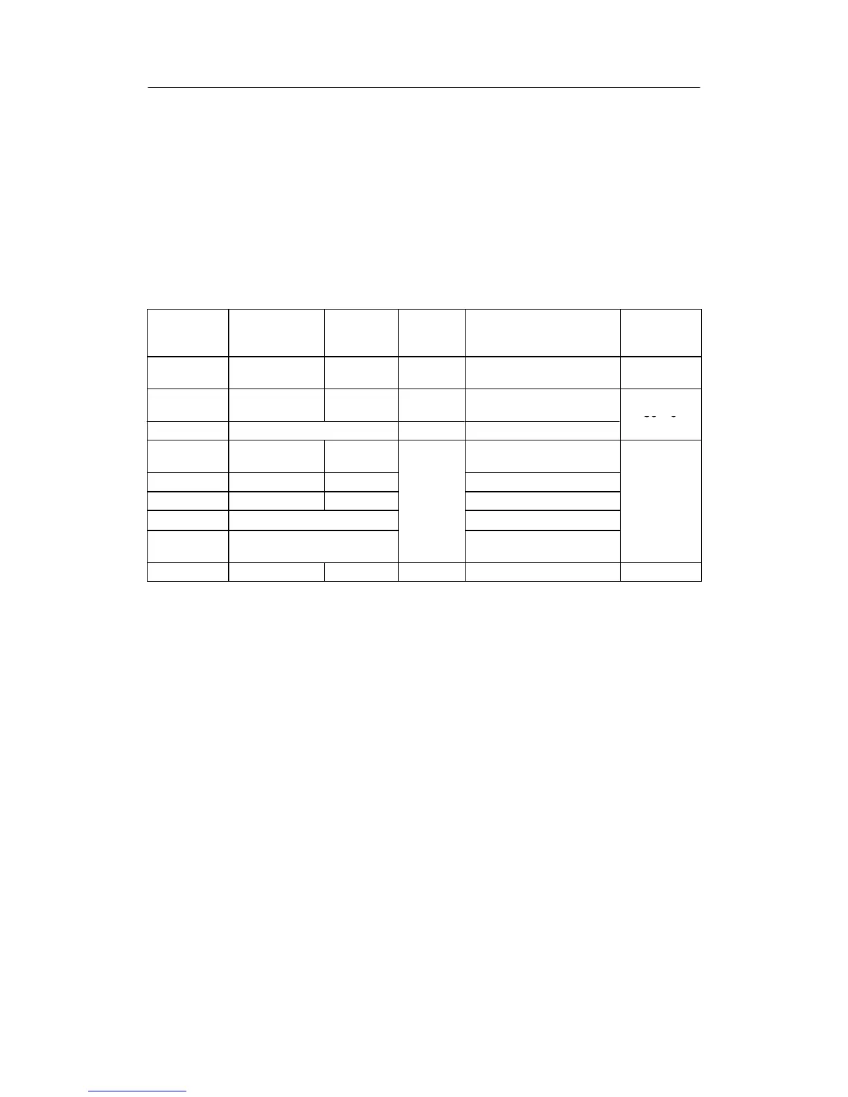
D The following parameters are available in the CAE3 menu for setting the measuring
range and adjustment
y display
parameter
name
w/x display
setting range
Factory
setting
Display
unit
Meaning/function of
parameter
Display and
function only
at:
tb
1)
0 to 400.0 50
_C, _F, K
Reference temperature
external reference point
S8 = 2
Mr 0.00 to 99.99 10 Ω Measuring of RLn.
(Pt100-2L)
S8 = 5
Cr Difference value to Mr Ω Calibr. of RLn. (Pt100-2L)
e
4)
Calibr. Meas. range full
scale
PC
5)
no, YES, no C no C -- Preset Calibration S8 = 0 to 5
Table 5-7 CAE3-menu parameter list
1)
If no specified thermocouple type is selected with S9 = 10, the parameter tb has no effect.
2)
The set measuring range is transferred as a standardized number range from 0 to 1 to the controller.
If the measured value mode is to be displayed physically, the offline parameters
dP, dA and dE must be set accordingly.
3)
ForS8=0to5:ΔA, ΔE do not appear as own parameters. The correction values for calibrating the start or full scale
of the measuring range are arbitrary.
4)
For S8 = 6, 7 the unit of the CA/CE display is in %.
5)
ForS8=0to5:WithΔA=ΔE = 0, PC = no C is displayed, it is not possible to switch over with the Δw--keys (7), (8)
to PC = YES. By adjusting CA/CE, PC = no is displayed, switching to PC = YES is possible. If PC = YES is displayed
ΔA=ΔE = 0 can be set with the Enter key (press for approx. 3 s), whereupon PC = no C is displayed.
The corresponding settings of the CAE3 menu for the different signal transmitters are described
below.
The range and thus the current measured value can be corrected with the parameters CA/CE to
compensate tolerances of the transmitters or adjustments with other display instruments (for
S8=0to5).
To avoid measuring errors, the assembly instructions in chapter 4.2.2, page 130 and especially
the maximum permissible line resistances (see table 2-3, page 41) must be observed in the de-
termination of the measuring range.