4 Installation
4.2 Electrical Connection
Manual
SIPART DR21
C73000-B7476-C143-08
145
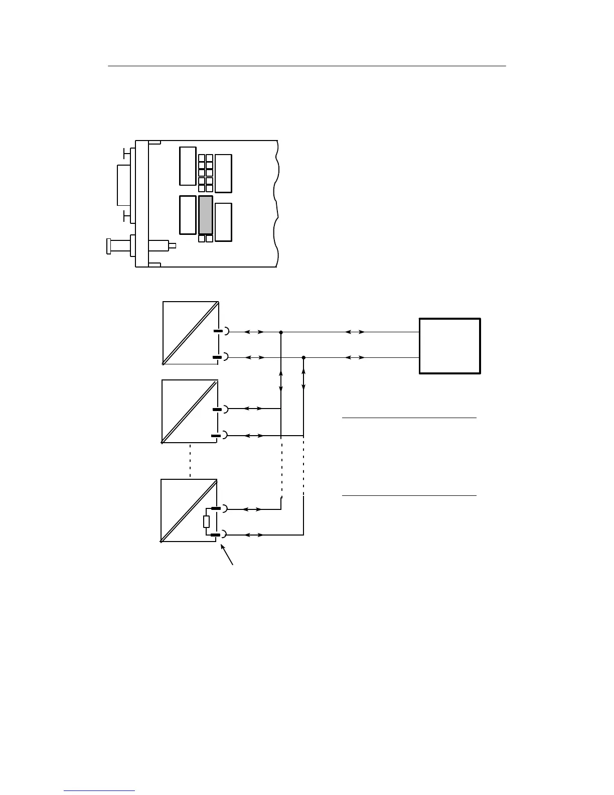
4.2.4.2 RS 485 bus
Can be inserted in slot 4, set structure switches S84 to S91 for transmission procedure.
RS 232
END/END
SIPART -
BUS
RS 485
RS 485
+150 R
Figure 4-40 Jumper settings SES-module 6DR2803-8C in RS 485 bus
Controller 32
RS 485 bus ≤1200 m
SES
Remote system
Controller 1
Controller 2
to
Rxd/Txd-B
Rxd/Txd-A
9-pin bus-plug for round cable: C73451-A347-D39
8 Rxd/Txd-A
8 Rxd/Txd-A
8 Rxd/Txd-A
3 Rxd/Txd-B
3 Rxd/Txd-B
3 Rxd/Txd-B
SES
SES
Jumper setting RS 485
Jumper setting RS 485 + 150R
Note line termination:
The RS 485-bus must be terminated with
its characteristic impedance. To do this,
the terminating resistor in the ”last” bus
user is switched by plugging the coding
bridge appropriately.
.
Figure 4-41 RS 485-bus connection