3 Functional description of the structure switches
3.4 Controller types (S1, S42 to S45)
Manual
SIPART DR21
C73000-B7476-C143-08
59
The analog displays have a fixed display range of 0 to 100 %. The overshoot or undershoot
is displayed by the flashing 100 % or 0 %-LED. This is displayed by one or two, alternately lit
LEDs. The centre point of the light field represents the ”pointer”. This display technique
doubles the resolution. If a falling characteristic (dE<dA) is set for the digital displays, the
analog displays are switched in direction of effect except for in the ratio controllers.
y-display
A 2-digit red digital display is available for the y-display additionally. The corresponding ad-
justment keys and status-LEDs are allocated to each other in color and space (see also
chapter 3.6, page 94 ).
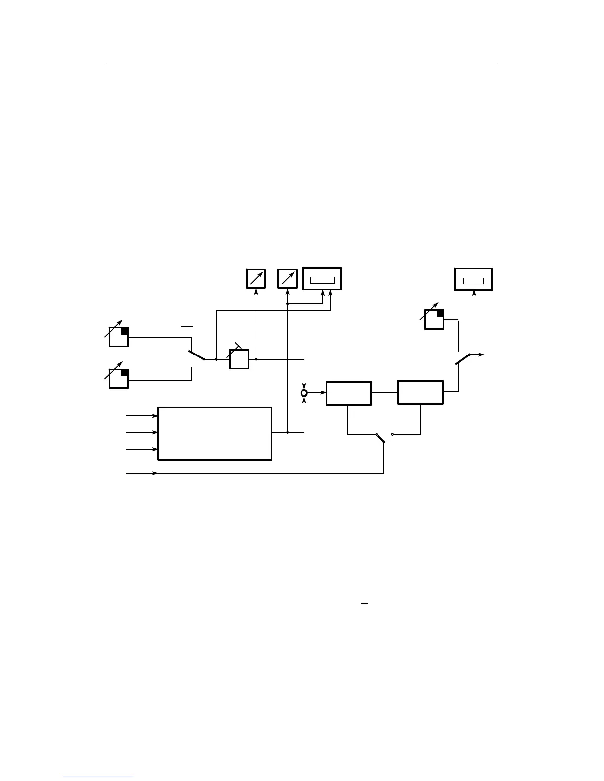
3.4.2 Fixed setpoint controller with 2 independent setpoints (S1 = 0)
ya
W
z
x3
x1
x2
ya+c6 S z
PID
W
+
-
wi2
wi1
INT∧CB
x=x1+c1S (x2 -c2Sx3+c3)
x
0000
tS
00
yH
y
x
Figure 3-5 Control principle S1 = 0
This controller type can be used as a fixed setpoint controller with 2 independent setpoints
(two batch mode) or as a fixed setpoint controller with 1 setpoint, by blocking the Internal/Ex-
ternal-switching (factory setting). By linking the inputs x1, x2, x3 with the constants c1, c2,
c3 it can be used as a one-, two- or three-component controller.
Switching between the two setpoints which can be set separately on the front panel takes
place dependent on the control signals Int and CB according to table 3-1, page 60. Signaling
of the active setpoint takes place on the LEDs Internal and C
. As soon as a LED lights, wi2
is active.