3 Functional description of the structure switches
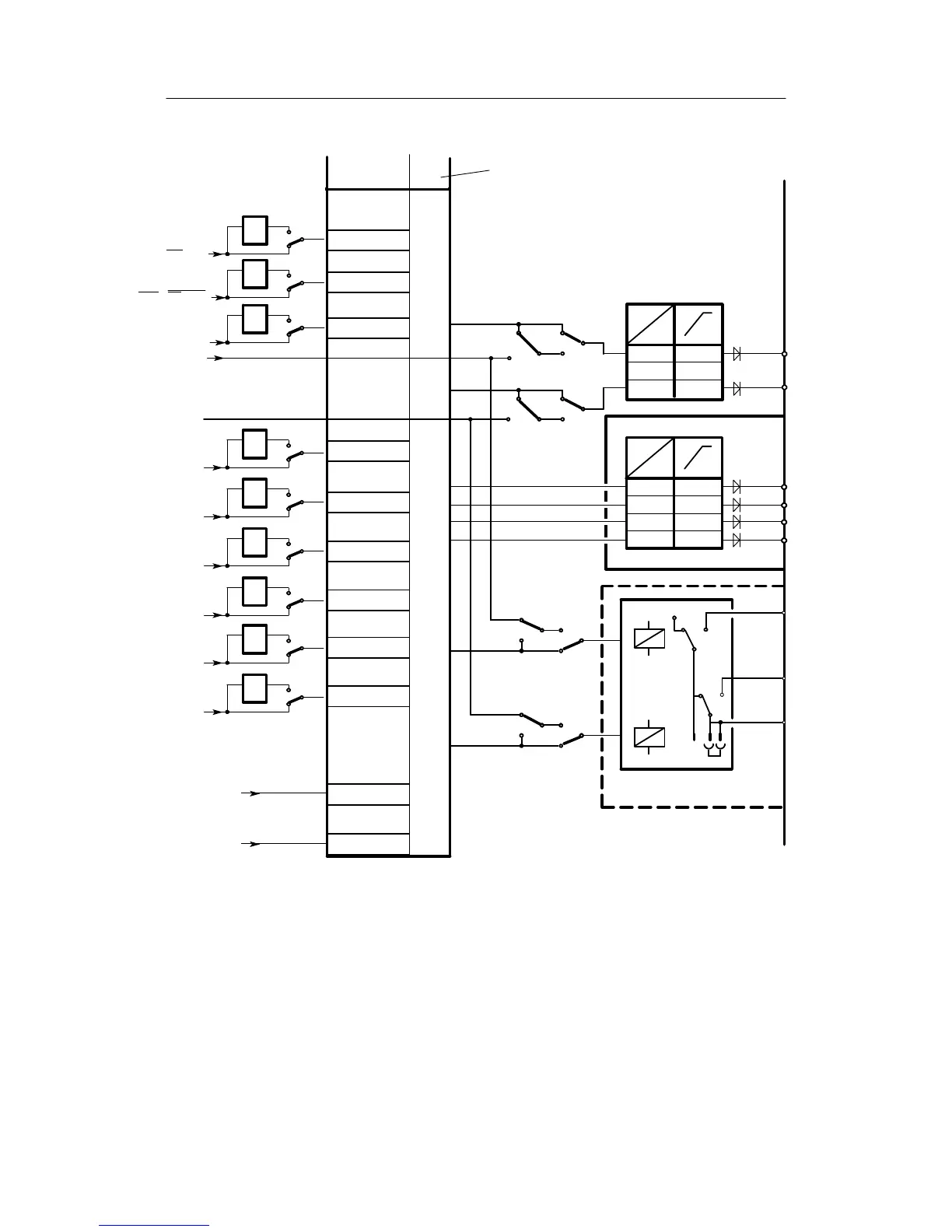
3.8 Digital output signal processing (S57 to S75)
Manual
112
SIPART DR21
C73000-B7476-C143-08
No assignment DO’s = 0
2)
3)
S**
Assignment
with
S58
S59
S60
S61
S62
S63
S64
S65
S66
S67
- Δy
Nw
A1
A2
A3
A4
MUF
Structure-
switch
S68
+Δw
-Δw
Structure switch position
DO7
DO8
4)
0/2
1/3
0
1/2/3
S57
S2
0/3
1/2
0
1/2/3
S57
0/2
1/3
S57
1/2/3
0
S2
0/3
1/2
S57
1/2/3
0
S2
S69
1
0
--1
S70
1
0
--1
S71
1
0
--1
RB
=Int
RC
=Int∧CB
H
+Δy
1
0
--1
DO1
DO2
1/7
1/8
5V
24 V
I
No assignment DOs = 0
2)
No assignment DOs = 0
2)
S72
1
0
--1
S73
1
0
--1
S73
1
0
--1
S74
1
0
--1
S74
1
0
--1
S75
1
0
--1
1
2
3/3
3/4
3/5
3/2
5V
24 V
I
Slot 3
DO3
DO4
DO5
DO6
4DO+2DI S22=1
1)
3
4
5
6
1/15
1/14
1/13
7
8
0
1)
When using 2DO-relay 35 V, 6DR2801-8A (S22 = 3), only DO3 and DO4 are available.
2)
At S**=0 there is no assignment, the digital outputs are then 0 and can be set at S85 = 2 by the SES.
3)
Assignment of different control signals to one digital output causes an OR-function.
4)
Message signal active tracking mode see page 1 11.
Figure 3-30 Assignment of digital outputs (S57 to S75)