4 Installation
4.2 Electrical Connection
Manual
130
SIPART DR21
C73000-B7476-C143-08
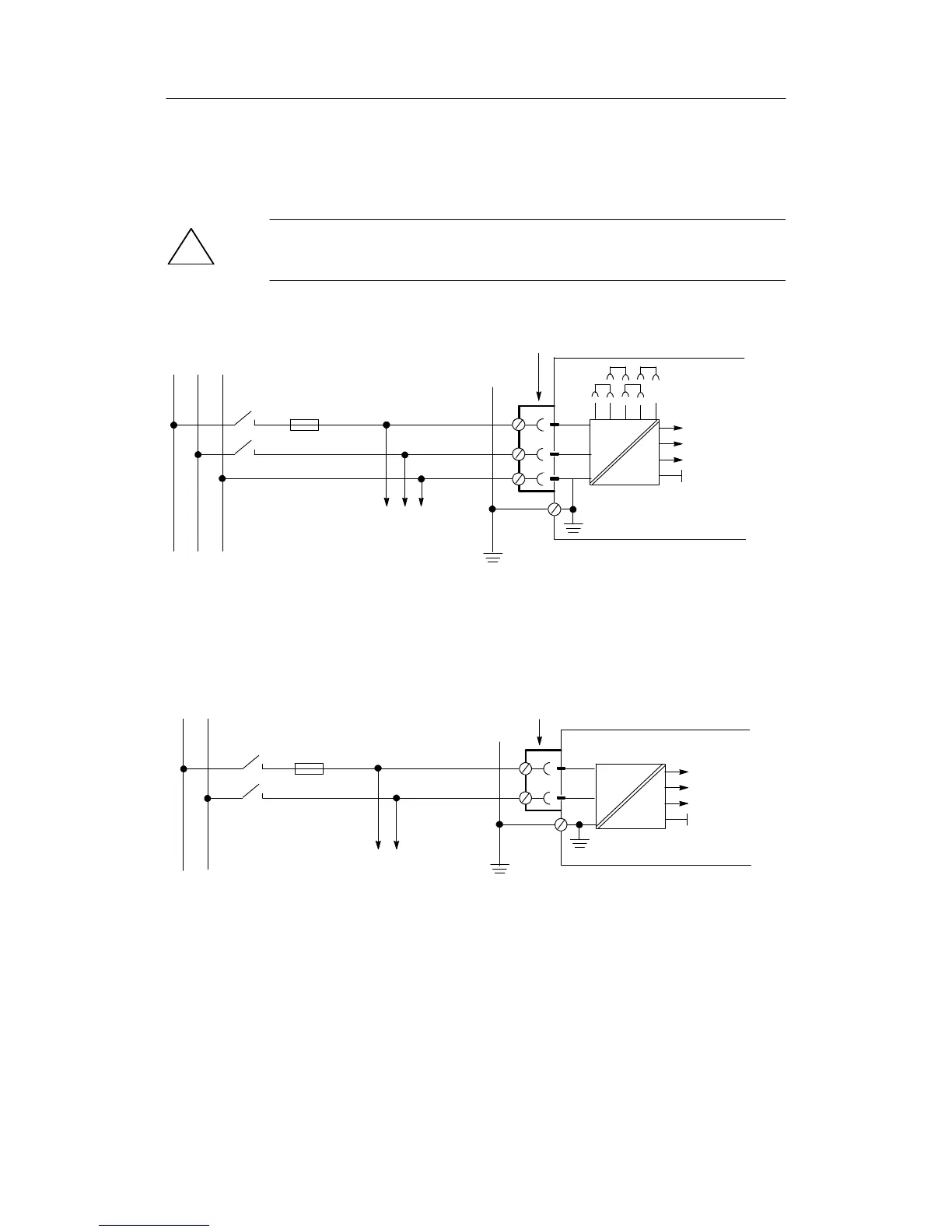
4.2.2 Connection standard controller
D Power supply connection
!
CAUTION
Pay attention to mains jumpering (see figure 4-2, page 122)!
- 6DR210x-5 (115/230 V AC)
=
+24 V
+5 V
U
REF
0.63 A slow-blow at 115 V
0.315 A slow-blow at 230 V
per controller
1)
L
N
Three-pin plug IEC 320 IV DIN 49457A
230 V
115 V
PE
LNPE
115 or 230 V AC
DR21
6DR210x-5
Fusing of the supply line
to VDE 041 1 part 1
EN61 010, part 1 max. 150 VA
Other loads on the same
control loop
Figure 4-10 Connection 115/230 V AC power supply
- 6DR210x-4 (24 V UC)
=
1.6A, slow-blow
per controller
1)
L
N
Special 2-pin plug, any polarity
U
L
=24VUC
+24 V
+5 V
U
REF
Fusing of the supply line
to VDE 041 1 part 1
EN61 010, part 1 max. 150 VA
or U
L
≤30 V
Other loads on the same
control loop
DR21
6DR210x-4
Figure 4-11 Connection 24 V UC power supply
1)
The connection between the PE conductor screw (figure4-8, item 5, page128) to ground must be established addition-
ally for high electromagnetic compatibility (EMC) in 115/230 V-controllers.
This connection must also be low resistive for high frequencies (Cu-band or Hf-strand). Alternatively at least 2.5 mm
2
flexible should be used.