4 Installation
4.2 Electrical Connection
Manual
SIPART DR21
C73000-B7476-C143-08
147
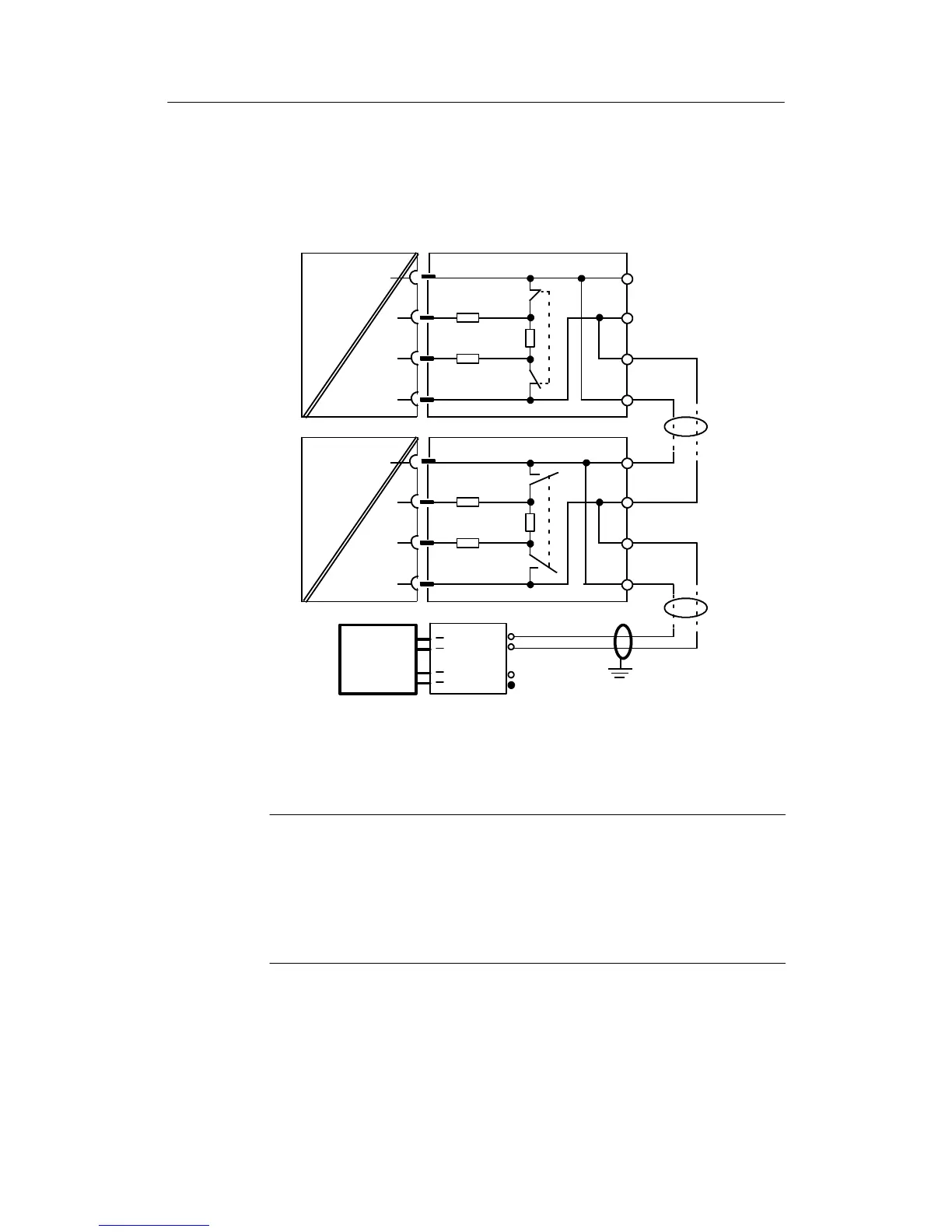
D Connecting the interface PROFIBUS-DP, 6DR2803-8P
Connection
Can be inserted in slot 4, set structure switches S84 to S91 for transmission procedure.
B
A
A
RxD/TxD-P
VP
390R
3
6
ON
DGND
5
220R
390R
PROFIBUS-
module
PROFIBUS-plug
Controller 1
(Slave)
RxD/TxD-N
8
B
Controller n
(Slave)
to
RxD/TxD-P
VP
390R
3
6
OFF
DGND
5
220R
390R
RxD/TxD-N
8
B
A
A
B
PROFIBUS-
module
RxD/TxD-A
RxD/TxD-B
Master
n max. number of controllers, dependent on master, max. 122
6ES7 972-
6ES7 972--
Switch
ON
Figure 4-42 Block diagram SIPART DR21 via PROFIBUS-DP and bus plug to master
.
NOTE line termination:
The RS 485-bus must be terminated with a characteristic impedance. To do
this, the switch in the bus connector must be switched ”ON” in the ”first” and
”last” bus users. The switch may not be ”ON” in any of the other bus users. A
detailed description and notes on cable laying and bus cable laying can be
found in the manual “ET 200 Distributed I/O System” order number
6ES5 998-3ES22.