2 Technical Description
2.3 Features
Manual
22
SIPART DR21
C73000-B7476-C143-08
D Digital outputs
T wo digital outputs, active, potential-bound.
It can be upgraded to four or six digital outputs with signal converters.
The digital outputs are loadable up to 30 mA per output for direct tripping of relays.
The digital outputs can also be used for the variable output, the relay outputs are then free
for any digital signal output.
The following controller-internal switching signals can be assigned to the digital outputs or
relays.
RB
Computer standby
Message that the controller can be switched to the external setpoint by the
CB-signal.
RC
Computer operation
Message that the controller is presently in computer operation or that it has
been switched over to the external setpoint by the CB-signal.
H Manual mode
Message that the controller has been switched over to manual mode with the
Manual/Automatic key.
Nw Tracking operation active
Message that the controller is in tracking operation.
A1 bis A4 Alarm output Alarm 1 to Alarm 4
MUF group alarm transmitter fault
The instruments’s analog input signals can be monitored for exceeding of the
measuring-range. This signal gives a group alarm if an error is detected.
Δw Output of switching signals for setpoint adjustment
This function is only active when the controller is structured as a control unit
(S1=4).
Δy Output of the incremental y-adjustment
Assignment is only possible on DO1, 2, 7 or 8 (S57).
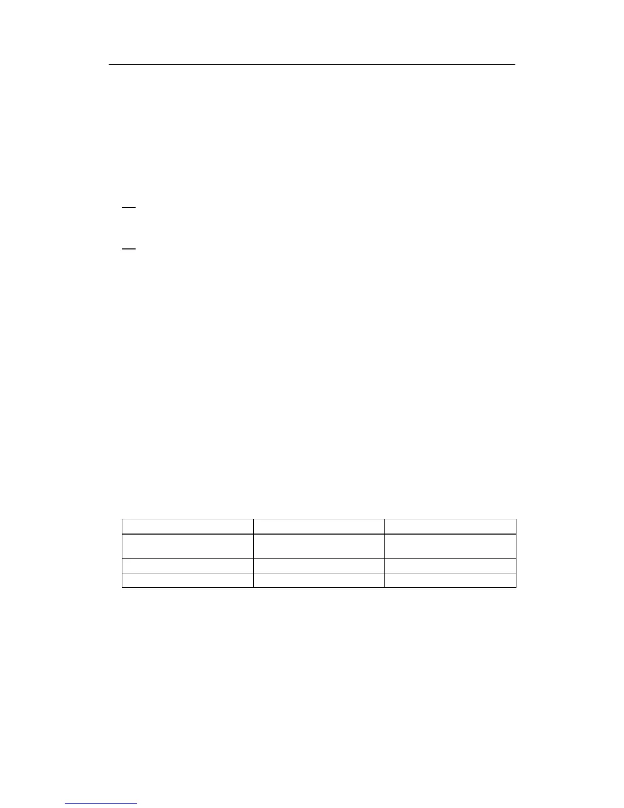
The following signal converters are available for extending the digital inputs and outputs:
Use on Description
4 x DO/2 x DI Slot 3 4 binary outputs 24 V
2 binary inputs 24 V
5xDI Slot 3 5 binary inputs 24 V
2xrelays Slot 3 2 relay outputs 35 V
D Serial interface
An interface can be retrofitted with signal converters for RS 232/RS 485 or PROFIBUS DP.