4 Installation
4.2 Electrical Connection
Manual
SIPART DR21
C73000-B7476-C143-08
137
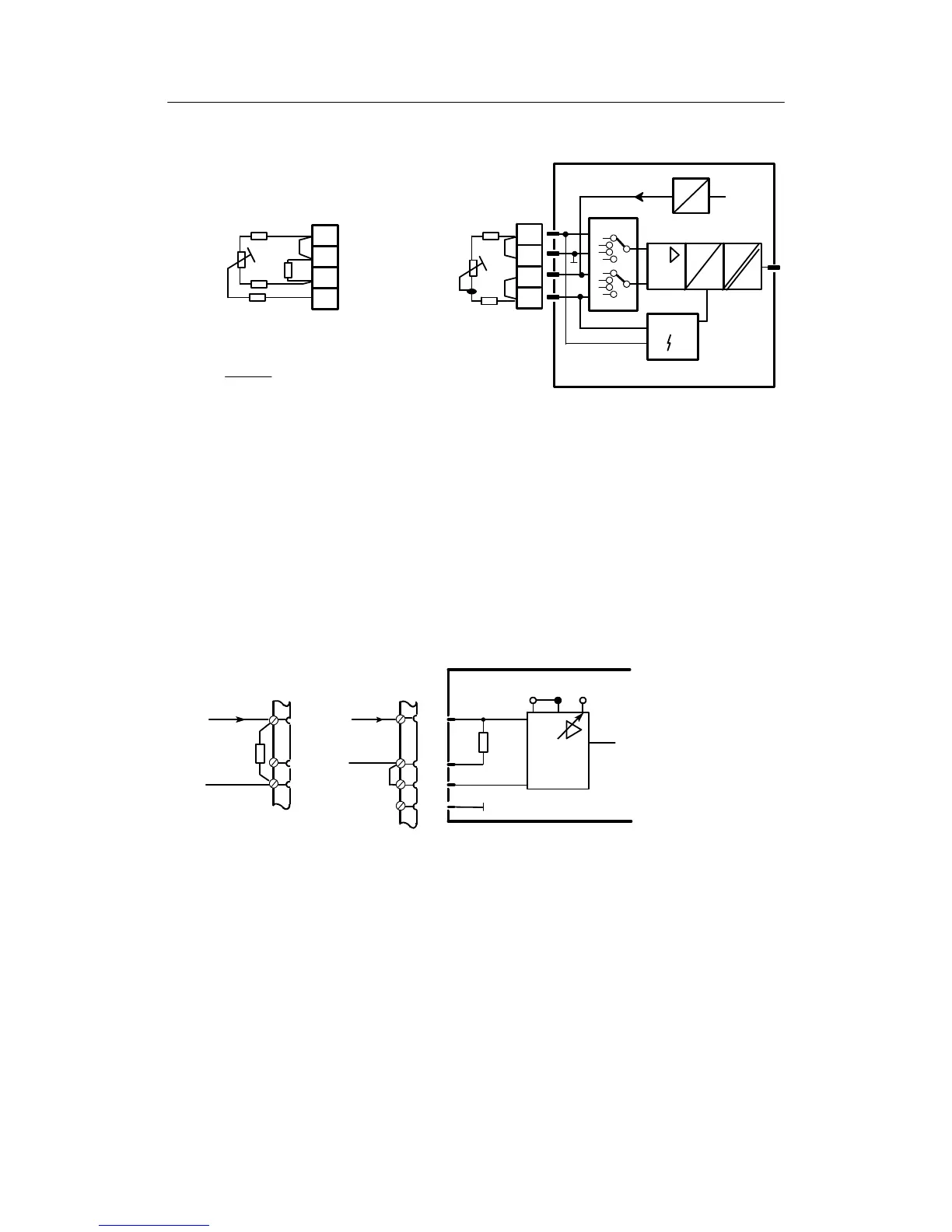
- Pin assignment for resistance potentiometer R S8 = 6, 7
2-Conductor terminal3-Conductor terminal
Block diagram of UNI-module 6DR2800-8V
R
L4
Rp
R
L1
R
L4
Rp
R
L1
R
L2
1)
R
s
R
L4
≤50 Ω R
L1
+R
L4
≤50 Ω
1)
R
s
Shunt impedance only necessary if 2.8 kΩ <R≤ 5kΩ
R
S
⋅R
p
R
S
+R
p
≤2,8k, Rp>5KΩ not recommended
i
m
U
+REF
+
--
A
D
Sensor
6DR2800-8V
4
3
2
1
4
3
2
1
Figure 4-23 Connection UNI-module AI3 S8 = 6, 7
4.2.3.2 Connection examples for analog measuring inputs with the module
6DR2800-8J
In current inputs the input load resistance is between AI+ and AI--.
If the signal is still required during service work in which the terminal is disconnected, the input
load resistance must be connected to the terminal between AI+ and AI--. The internal 49.9 Ω
resistance must then be disconnected in 6DR2800-8J by appropriate rewiring.
AI+
AI -
20 mA
49.9 Ω
1V/10V
--
+
49.9 Ω
optionally
6DR2800-8J
AI+
AI -
20 mA
4
3
2
1
set 1 V jumper
Figure 4-24 Current input via options modules, internal or external 49.9 Ω resistance