5 Operation
5.5 CPU self-diagnostics
Manual
SIPART DR21
C73000-B7476-C143-08
179
5.5 CPU self-diagnostics
The CPU runs safety diagnostics routines which run after only one reset or cyclically. The CPU
is familiar with two different types of reset:
Power On--Reset
always take place when the 5 V supply drops below 4.45 V, i.e. the power supply is interrupted
for longer than specified in the technical data.
All parameters and structures are reloaded from the user program memory into the RAM. The
current process variables and the controller status are reloaded from the EEPROM for these
data.
At S83 = 1 the digital w/x- display flashes as an indication after a Power-On-Reset, acknowl-
edgement is by the Shift key (6) for w/x digital display.
With S83 = 0, the flashing is suppressed.
W atch_dog Reset
The processor has an integrated watchdog which monitors the cyclic program runs indepen-
dently.
When a watch-dog reset occurs the parameters and structures from the user program memory
are loaded into the RAM. The current process variables and the controller status are read out of
the RAM for further processing.
There are no flashing signals on the front module.
tESt appears for a maximum 5 s in the digital w/x display after every reset.
Every detected error of the self--monitoring leads to a flashing error message on the digital w/x
display with defined states of the analog and digital outputs.
The reactions listed in the table are only possible of course (since this is a self-test) if the errors
occur in such a way that the appropriate outputs or the front module are still controlled properly
or the outputs themselves are still functioning.
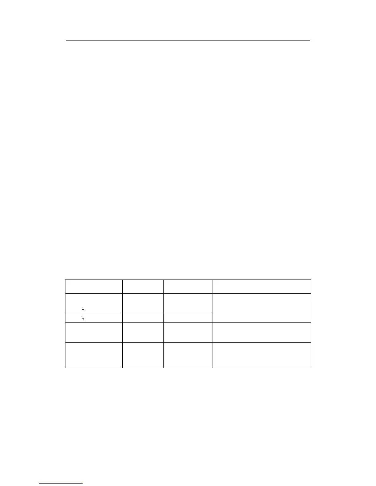
Error message w/x
display
Monitoring of Monitoring time Primary cause of the error/remedy
during monitoring tESt
inthecaseofanerror
CPU
EEPROM,
RAM, EPROM
after every reset
monitored components of the CPU or
EEPROM de
OP.1.* 1) Data communi-
cation slot 1:
UNI-module
cyclic Option not plugged, defective or S6
does not correspond to plugged option /
plug or change option or c orrect S6.
OP.*.3 1) Data communi-
cation slot 3
4DO + 2DI or 5
DI option
cyclic Option not plugged, defective or S22
does not correspond to plugged
option / plug or change option or correct
S22
2)
1)
also double error display OP.1.3 possible. * means digit dark
2)
If 2DO relay is selected with S 22 = 3, no monitoring takes place.
At DI3 to DI7, S22 = 2 the effect of the digital inputs (after inversion) are set to 0 in the event of an error.
Table 5-8 Error message of the CPU